I'd like to get opinions on building an attenuator that uses modern analog switches or a multiplying DAC. I've seen this method mentioned a few times and one example of a finished product but it seems it is still rarely done by the DIY community.
After searching through the forums there seems to be a lot of opinions on solid state attenuation but it looks like much of it is not based actual experience. It also seems that analog switches have a reputation that was gained 10 years ago but the analog switches available today are quite different, some having RON of < 1R.
The basic principle seems to be: VI conversion > R2R attenuation > IV conversion. There are quite a few very high end preamps that use this method, eg:
- Mark Levinson 32 and 38 preamps: Pic here.
- Luxman Luxman Electronically Controlled Ultimate Attenuator (LECUA, used is multiple products): Details here
- Accuphase AAVA: Discussed briefly here.
bbp built one, details here and here. Looks like it achieved very good results but he never shared the whole schematic.
While these implementations might sound complex with many analog switches and some ICs to control them, the same can be achieved with a single DAC and Opamp IC. Mark Levinson also does this. BV has mentioned a couple of times that he has achieved good results with DAC8043. It is detailed in the datasheet in figure 3 (VREF is the input):

Here is an Analog Devices Circuit Note about using this method for attenuation: Circuit Note | CN0025 | Precision, AC Reference Signal Attenuator Using the AD5546/AD5556 Multiplying DAC | Analog Devices
The DAC8043 might be good for testing as it comes in a DIP package but there would be better options once it was tested, like using AD5439 with ADuM7440 (SPI isolation) and a OPA1612.
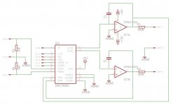
I've attached a schematic using a DAC7800 and a dual opamp.
What do you think? Anyone experimented with this? An SPI controlled 1024 step attenuator that is better and more flexible than a PGA2310 and easier to use than a CS3318?
After searching through the forums there seems to be a lot of opinions on solid state attenuation but it looks like much of it is not based actual experience. It also seems that analog switches have a reputation that was gained 10 years ago but the analog switches available today are quite different, some having RON of < 1R.
The basic principle seems to be: VI conversion > R2R attenuation > IV conversion. There are quite a few very high end preamps that use this method, eg:
- Mark Levinson 32 and 38 preamps: Pic here.
- Luxman Luxman Electronically Controlled Ultimate Attenuator (LECUA, used is multiple products): Details here
- Accuphase AAVA: Discussed briefly here.
bbp built one, details here and here. Looks like it achieved very good results but he never shared the whole schematic.
While these implementations might sound complex with many analog switches and some ICs to control them, the same can be achieved with a single DAC and Opamp IC. Mark Levinson also does this. BV has mentioned a couple of times that he has achieved good results with DAC8043. It is detailed in the datasheet in figure 3 (VREF is the input):
Here is an Analog Devices Circuit Note about using this method for attenuation: Circuit Note | CN0025 | Precision, AC Reference Signal Attenuator Using the AD5546/AD5556 Multiplying DAC | Analog Devices
The DAC8043 might be good for testing as it comes in a DIP package but there would be better options once it was tested, like using AD5439 with ADuM7440 (SPI isolation) and a OPA1612.
I've attached a schematic using a DAC7800 and a dual opamp.
What do you think? Anyone experimented with this? An SPI controlled 1024 step attenuator that is better and more flexible than a PGA2310 and easier to use than a CS3318?
Attachments
No replies but I tested it myself 🙂
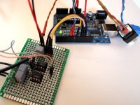
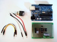
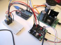
I got a DAC8043 from Ebay and used half of an OPA2132 to make the circuit posted above (Figure 3). I wrote some Arduino code to control the DAC to make a 4096 step attenuator!
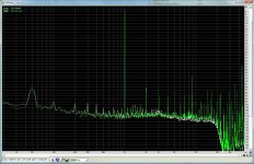
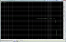
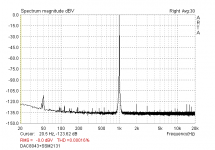
It works really well. I tested it with headphones and then ran some RMAA tests. These tests were just using the onboard line in from my motherboard so its not very good but allowed me at least some basic comparison. In the attached measurements the Left channel is just looped back and the Right channel goes through the R2R attenuator. Better than I thought it would be considering it was on perf board with long cables going everywhere and poor grounding arrangement.
I think I might now design a test PCB for a version with an AD5439 with ADuM7440 (SPI isolation).
I got a DAC8043 from Ebay and used half of an OPA2132 to make the circuit posted above (Figure 3). I wrote some Arduino code to control the DAC to make a 4096 step attenuator!
It works really well. I tested it with headphones and then ran some RMAA tests. These tests were just using the onboard line in from my motherboard so its not very good but allowed me at least some basic comparison. In the attached measurements the Left channel is just looped back and the Right channel goes through the R2R attenuator. Better than I thought it would be considering it was on perf board with long cables going everywhere and poor grounding arrangement.
I think I might now design a test PCB for a version with an AD5439 with ADuM7440 (SPI isolation).
Attachments
That’s a really nifty solution. One thing that worries me is that the attenuation is linear, so if you want an audio (logarithmic) attenuator you must throw away some steps. With 4096 steps not a big deal, however the microcontroller must:
a) Store a table of the log steps, I am a programmer (JAVA) but I have never done micro controllers, but I believe the memory is limited.
b) Calculate the next step on the fly. Having the log function in an 8-bit micro controller this may be slow.
I am sure a solution can be found, maybe external memory. I wonder how many steps remain. I am surprised the dac Vref input can swing below zero.
Yep I am aware of this 🙂 I haven't really tried to solve it yet but I'm sure it won't be hard using either a mathematical log function or a lookup table using selected steps from the 4096 available.
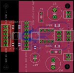
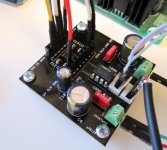
I've just designed a PCB for testing a AD5439, ADuM7440 and a DIP opamp. It's been sent to a PCB fabricator in China, should be back in a week or two.
I've just designed a PCB for testing a AD5439, ADuM7440 and a DIP opamp. It's been sent to a PCB fabricator in China, should be back in a week or two.
Attachments
I used it since 2000 to 2005, with very good results, it is better than specialized IC´s (see attachment) like WM8816 or PGA. With stored table , 90steps about 1dB and mute it works very comfortable. Now I am using low impedance (1kohm) relay attenuator.
Did you use DAC8043 in this graph?
Cool. Did you have any issues with the implementation? Turn on pop/thump? PCB layout issues? Did you use isolation from the micro controller?
No problems with implementation (reset and mute at turn on for 1-2 seconds), also no galvanic isolation from microcontroller. But analog and digital grounds connected only in one point, as close as possible to noniverting inputs to OA.
I have calculated a table here. It seems it would work fine for attenuation to -50dB even -60dB, then runs out of bits. Which is fine for most audio applications. Though I must confess in my heart I was hoping for 0.1dB resolution (even though overkill) to -100dB.
You could do this with logarithmic relay dividers. I guess it’s a tradeoff between added space and cost and relay noise.
db_____attenuation_____Dac_bits
0______1_____________4096
-1_____0.891250938____3651
-2_____0.794328235____3254
-3_____0.707945784____2900
-4_____0.630957344____2584
-5_____0.562341325____2303
-6_____0.501187234____2053
-7_____0.446683592____1830
-8_____0.398107171____1631
-9_____0.354813389____1453
-10____0.316227766____1295
-11____0.281838293____1154
-12____0.251188643____1029
-13____0.223872114____917
-14____0.199526231____817
-15____0.177827941____728
-16____0.158489319____649
-17____0.141253754____579
-18____0.125892541____516
-19____0.112201845____460
-20____0.1____________410
-21____0.089125094____365
-22____0.079432823____325
-23____0.070794578____290
-24____0.063095734____258
-25____0.056234133____230
-26____0.050118723____205
-27____0.044668359____183
-28____0.039810717____163
-29____0.035481339____145
-30____0.031622777____130
-31____0.028183829____115
-32____0.025118864____103
-33____0.022387211____92
-34____0.019952623____82
-35____0.017782794____73
-36____0.015848932____65
-37____0.014125375____58
-38____0.012589254____52
-39____0.011220185____46
-40____0.01___________41
-41____0.008912509____37
-42____0.007943282____33
-43____0.007079458____29
-44____0.006309573____26
-45____0.005623413____23
-46____0.005011872____21
-47____0.004466836____18
-48____0.003981072____16
-49____0.003548134____15
-50____0.003162278____13
-51____0.002818383____12
-52____0.002511886____10
-53____0.002238721____9
-54____0.001995262____8
-55____0.001778279____7
-56____0.001584893____6
-57____0.001412538____6
-58____0.001258925____5
-59____0.001122018____5
-60____0.001__________4
-61____0.000891251____4
-62____0.000794328____3
-63____0.000707946____3
-64____0.000630957____3
-65____0.000562341____2
-66____0.000501187____2
-67____0.000446684____2
-68____0.000398107____2
-69____0.000354813____1
-70____0.000316228____1
-71____0.000281838____1
-72____0.000251189____1
-73____0.000223872____1
-74____0.000199526____1
-75____0.000177828____1
-76____0.000158489____1
-77____0.000141254____1
-78____0.000125893____1
-79____0.000112202____0
-80____0.0001_________0
-81____8.91251E-05____0
-82____7.94328E-05____0
-83____7.07946E-05____0
-84____6.30957E-05____0
I see your point. Thanks for the table!
In my testing without any conversion, ie just using a linear scale (but obviously skipping many steps) it actually wasn't that bad. I'm thinking using a more relaxed curve will give more steps and still be very usable.
Or, use a bit DAC IC 😉
In my testing without any conversion, ie just using a linear scale (but obviously skipping many steps) it actually wasn't that bad. I'm thinking using a more relaxed curve will give more steps and still be very usable.
Or, use a bit DAC IC 😉
Sure,
The Formula is:
attenuation=10^(db/20)
where db is a negative number for attenuation and a positive number for gain
Then you take this and multiply by the (range of the dac) * (attenuation)
I just used a spreadsheet.
The only one I remember -6db is about half.
The Formula is:
attenuation=10^(db/20)
where db is a negative number for attenuation and a positive number for gain
Then you take this and multiply by the (range of the dac) * (attenuation)
I just used a spreadsheet.
The only one I remember -6db is about half.
Last edited:
I used it since 2000 to 2005, with very good results, it is better than specialized IC´s (see attachment) like WM8816 or PGA. With stored table , 90steps about 1dB and mute it works very comfortable. Now I am using low impedance (1kohm) relay attenuator.
Sure,
The Formula is:
attenuation=10^(db/20)
where db is a negative number for attenuation and a positive number for gain
Then you take this and multiply by the (range of the dac) * (attenuation)
I just used a spreadsheet.
The only one I remember -6db is about half.
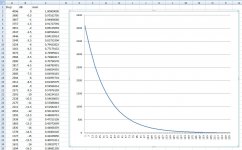
Thanks for the formula. So I tried attenuation=10^(db/40) and got this curve and ~200 0.5dB steps.
Won't know how well it will work until I get the PCBs and test it though.
Attachments
Yes, indeed. However, this isn't a complicated task and most micros will have plenty of memory. I use Microchip PICs and most of them can be had with more memory. It's the same part, but with more FLASH and slightly higher cost.a) Store a table of the log steps, I am a programmer (JAVA) but I have never done micro controllers, but I believe the memory is limited.
It'll be extremely slow. I suggest a lookup table. You calculate all the possible logs (I use Excel) and then store the results in a table. Since you're not doing much else, you'll actually have more than enough capability on most small uC's.b) Calculate the next step on the fly. Having the log function in an 8-bit micro controller this may be slow.
Last edited:
maxw,
Check your calculation table, -6db should equal half -0.5 input voltage
10^(-6/20) = 0.50118723362727228500155418688495
This should be achieved at half scale in the dac or (4095/2)
0b111111111111 = full scale (-0db)
0b011111111111 = -6db
You can make up your own curve to make it more of a log taper, as you have, making the step sound more linear to the ear, but your changing the formula for dB that you can not do. It would be like me saying ohms law is E=I2R.
FoMoCo,
This is what I figured. Trying to figure out how to do that calculation in integer math was messing with my head anyway. Math is not my strong point. Seem to have forgotten everything.
I am arm-chair engineering this for now (may just byte the bullet and buy dac with remote volume control) but I am thinking about a universal controller board integrating display (you can see from far), rotary encoder connection and connector(s) to volume control board.
This may or may not work...
I once had an idea to use multiple attenuators that are scaled by a factor of 2. Say... -1dB, -2dB, -4dB, -8dB, -16dB, and so forth. Use an analog switch to select or bypass each one, with its control tied to each bit of a binary word. This way the word is directly translated to an attenuation value.
I once had an idea to use multiple attenuators that are scaled by a factor of 2. Say... -1dB, -2dB, -4dB, -8dB, -16dB, and so forth. Use an analog switch to select or bypass each one, with its control tied to each bit of a binary word. This way the word is directly translated to an attenuation value.
maxw,
Check your calculation table, -6db should equal half -0.5 input voltage
10^(-6/20) = 0.50118723362727228500155418688495
This should be achieved at half scale in the dac or (4095/2)
Yes, you are right 🙂 Ignore the dB column in my table. My curve actually gives 0.25dB steps down to -41.75 and then the steps get steadily larger.
This one looks interesting. I was looking into solid state attenuators before, but newer technology could bring better results than before.
Got the PCBs, put them together and wrote some Arduino code and tested it just now. It works! Smooth volume changes, no clicks or pops. I've only tested with headphones though. Haven't taken any measurements yet and not really sure my equipment is worth using for measurements anyway. Will do more testing in the coming days 🙂
Attachments
I suggest a lookup table. You calculate all the possible logs (I use Excel) and then store the results in a table. Since you're not doing much else, you'll actually have more than enough capability on most small uC's.
I agree. That's exactly how I did it. The log function is much more "memory expensive" for a microcontroller than a lookup table is, and the table is faster too.
- Home
- Source & Line
- Analog Line Level
- Solid state R2R attenuator using analog switches or multiplying DAC