I do not assume it to die, only do not have time enough to be present permanently.
Even if I measure the sample and want to get rid of mains harmonics, I have to put the PCB on large Al plane connected to AGND. Though the PCB has its own groundplane. Also, groundloop constituted by input stereo RCA cable, if cable grounds are connected at source, raises hum - input signal level is just mV and less.
I am waiting for housing delivery (estimated next week) to get more results.
I guess you could have your software present a SNR number from the same dist measurement graph you presented earlier. Maybe even A-weigted?
Noise spectral density often is higher at low freq but more constant at higher freq, ie it is not a constant but a function of frequency which can be seen in any OPamp or transistor circuit,
so you cannot just multiply en by BW to get a noise voltage.
You have to integrate en over the freq range to get a voltage.
Actually you have to integrate en^2 and then take the square root of the sum from the integration, as noise is summed by taking the square root of summed squared en:s.
If you only have resistros that only produce thermal noise, en is of course a flat line.
Once, you have that voltage,
one can calculate SNR for a certain output voltage.
I helped Spectrum Software develop a technique for getting the total rms noise voltage over a given BW. In MicroCap you enter a statement in AC analysis like:
Sqrt(SD(Onoise**2))
where SD is a summing function,
and the Y-value at the highest freq (in the freq BW),
is the total rms noise voltage for a circuit.
Examples and full text (written by Bill at Spectrum Software) can be found here How to simulate total rms noise voltage
Well,
I guess this is old news to most of the posters, but maybe some reader will find this useful.
Sigurd
How to simulate total rms noise voltage
Noise spectral density often is higher at low freq but more constant at higher freq, ie it is not a constant but a function of frequency which can be seen in any OPamp or transistor circuit,
so you cannot just multiply en by BW to get a noise voltage.
You have to integrate en over the freq range to get a voltage.
Actually you have to integrate en^2 and then take the square root of the sum from the integration, as noise is summed by taking the square root of summed squared en:s.
If you only have resistros that only produce thermal noise, en is of course a flat line.
Once, you have that voltage,
one can calculate SNR for a certain output voltage.
I helped Spectrum Software develop a technique for getting the total rms noise voltage over a given BW. In MicroCap you enter a statement in AC analysis like:
Sqrt(SD(Onoise**2))
where SD is a summing function,
and the Y-value at the highest freq (in the freq BW),
is the total rms noise voltage for a circuit.
Examples and full text (written by Bill at Spectrum Software) can be found here How to simulate total rms noise voltage
Well,
I guess this is old news to most of the posters, but maybe some reader will find this useful.
Sigurd
PMA said:60 - 70dBA is pretty good. It is over whole audio band. One must not get confused by results of narow band spectral analysis (my is 65536 points at Fs = 48kHz, so analysis bandwidth is 0.73Hz). Noise spectral density and noise, not the same issues, noise density is to be multiplied by rtBW, where BW is 20kHz. And A weighted.
How to simulate total rms noise voltage
Power Supply
And, do not forget about the power supplies!
How much noise can we allow a power supply for a MC RIAA amp to have before it is the PS noise that is dominant over the amplifier's noise level?
Sigurd
And, do not forget about the power supplies!
How much noise can we allow a power supply for a MC RIAA amp to have before it is the PS noise that is dominant over the amplifier's noise level?
Sigurd
jam said:PMA,
...........this thread is too good to let die. We have not covered shielding and grounding yet...........anyone care to continue.
Jam
Sigurd Ruschkow said:
so you cannot just multiply en by BW to get a noise voltage.
Yes, I know. You can read quite enough from the graph posted.
Re: Power Supply
Sure I do not.
Sigurd Ruschkow said:And, do not forget about the power supplies!
Sure I do not.
Good post, Nuvistor!
AN-104 is a must read for those interested in noise behaviour in RIAA amplifiers and/or what A-weighting does to SNR.
The calculations for A-weighted SNR for a RIAA amp operating at 50 - 12 500 Hz, and driven by a MM cartridge are.... rather complex. To end up with the SNR of 69.3dB will probably take....a few hours.
I am glad that MicroCap will do it in a matter of seconds 🙂
Sigurd
nuvistor said:An excellent short treatise on audio noise analysis applied to MM RIAA preamp design from National Semiconductor, 1974:
National Semiconductor AN-104 - Noise Specs Confusing?
Sigurd Ruschkow said:The calculations for A-weighted SNR for a RIAA amp operating at 50 - 12 500 Hz, and driven by a MM cartridge are.... rather complex. To end up with the SNR of 69.3dB will probably take....a few hours.
I am glad that MicroCap will do it in a matter of seconds 🙂
Sigurd
SPICE noise calculations are very handy but are only as good as the noise models for the active devices, which at best are hit-or-miss and typically are unreliable as offered by component and software vendors. JFET models appear to match datasheet values better than BJT models.
Many OPamps have good models for noise, and if you have the datasheets (or can measure the devices) you can create models
from this data.
To do manual calculations you need this data, too,
so I do not understand
why one wants to spend hours on this.....and that over and over again......
Sigurd
from this data.
To do manual calculations you need this data, too,
so I do not understand
why one wants to spend hours on this.....and that over and over again......
Sigurd
nuvistor said:
SPICE noise calculations are very handy but are only as good as the noise models for the active devices, which at best are hit-or-miss and typically are unreliable as offered by component and software vendors. JFET models appear to match datasheet values better than BJT models.
Sigurd Ruschkow said:Many OPamps have good models for noise, and if you have the datasheets (or can measure the devices) you can create models
from this data.
Yes, there are good models, especially for low-noise op amps from about 1997 on, but "caveat emptor". I highly recommend validating noise models against datasheets or measured data with test simulations, like a voltage follower with zero source impedance. In this circuit, the 2N3904 model included in LTSpice with 200uA emitter current simulates at 1.2nV/rtHz at any frequency from 1Hz-20kHz, so 1/f noise is not modeled, and Rb=20, too low.
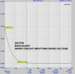
Attached is eq. short-circuit rms input noise for a AD797 using Analog Device's SPICE model and MicroCap9.
Compararing the simulation results with the datasheet rev F results in an exact match.
The AD797 is from the 80's I believe....
Regards,
Sigurd
Compararing the simulation results with the datasheet rev F results in an exact match.
The AD797 is from the 80's I believe....
Regards,
Sigurd
nuvistor said:
Yes, there are good models, especially for low-noise op amps from about 1997 on, but "caveat emptor". I highly recommend validating noise models against datasheets or measured data with test simulations, like a voltage follower with zero source impedance. In this circuit, the 2N3904 model included in LTSpice with 200uA emitter current simulates at 1.2nV/rtHz at any frequency from 1Hz-20kHz, so 1/f noise is not modeled, and Rb=20, too low.
Attachments
Jam -
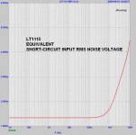
I downloaded the SPICE model for the LT1115 from Linear's web page, and installed it in MC. You see the results below.
It is way off. Instead of 1nV/sqrt(Hz) we see 1uV/sqrt(Hz).
Looking at the model data, I see no noise generator.
Sigurd
I downloaded the SPICE model for the LT1115 from Linear's web page, and installed it in MC. You see the results below.
It is way off. Instead of 1nV/sqrt(Hz) we see 1uV/sqrt(Hz).
Looking at the model data, I see no noise generator.
Sigurd
jam said:Sigurd,
Any idea how the LT1115 stacks up?
Jam
Attachments
Sigurd Ruschkow said:Jam -
I downloaded the SPICE model for the LT1115 from Linear's web page, and installed it in MC. You see the results below.
It is way off. Instead of 1nV/sqrt(Hz) we see 1uV/sqrt(Hz).
Looking at the model data, I see no noise generator.
Sigurd
Unfortunately, there are MANY that bad opamp models.
Looking at the numbers in the datasheet (high Ib, lowish input resistance, and superbly low noise) my educated guess is that it is bipolar input.
Sigurd
Sigurd
jam said:Thanks, I wonder what might be wrong. Is the LT1115 bipolar or fet input?
Jam
- Status
- Not open for further replies.
- Home
- Source & Line
- Analogue Source
- Solid state phono preamp design philosophy