PMA,
Looks good............where did you get that chassis from? and how is the project working out?
Jam
Looks good............where did you get that chassis from? and how is the project working out?
Jam
Hello all,
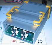
The board is made by Hammond, 145x series.
Otherwise, PMA is in vacation but don't be afraid, he's like Emile Zatopec able to working for a while.
Max
The board is made by Hammond, 145x series.
Otherwise, PMA is in vacation but don't be afraid, he's like Emile Zatopec able to working for a while.
Max
I'm surprised that Mr. Vogel's does not provoke more discussion, since it breaks with many 'audiophile laws'.
It's a radical approach that looks at each and any part of the circuit under the viewpoint of noise.
Rüdiger
It's a radical approach that looks at each and any part of the circuit under the viewpoint of noise.
Rüdiger
so pma, how's the riaa preamp work going ... ?
are you willing to share why you use LT1028 at first position instead of AD797?
also curious to know if you had more thoughts or experimental results on power supplies for the preamp yet ...
mlloyd1
are you willing to share why you use LT1028 at first position instead of AD797?
also curious to know if you had more thoughts or experimental results on power supplies for the preamp yet ...
mlloyd1
Walk Jung recently posted in another forum and stated thet the 1028 and 1115 are identical. The only difference is in GRADING-the ones that don't meet (the) stringent DC specs become 1115s.
Hi Pavel.
What gain does the first cascade have? ... You have MOSFET in second stage. It is more noise.
Best regards,
Alex
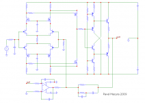
- Without the value of parts - a discussion does not make sense, results can be different. It is simpler to use OPAMs.So how about this? (Just an idea, some parts omitted).
What gain does the first cascade have? ... You have MOSFET in second stage. It is more noise.
Best regards,
Alex
That looks like your line amplifier. Is it not too noisy for
phono work?
Can you get the needed gain, ~84 dB at DC, with that topology?
phono work?
Can you get the needed gain, ~84 dB at DC, with that topology?
So how about this? (Just an idea, some parts omitted).
No the reason to avoid passive EQ is because it massively wastes headroom and requires lots of gain.
But it sounds better! 😛
Regards,
Andy
Not necessarily. It is mostly a superstition, that passive EQ 'sounds better'. Depends on implementation and active components used.
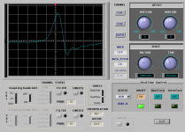
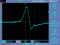
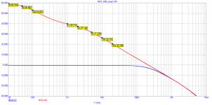
Interesting graphs Pavel.
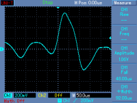
Its for this reason that I now favour fully active RIAA. I have done some sims, and with active/passive EQ, the best I can get off +-15V rails is about 200mV overload at 20KHz - and it will be worse ay higher frequencies. In the other hand, active EQ gives me 700mV at 20KHz.
I also took a look at the load on the op-amp output. Its doable at 20KHz, but if you take alook at 50KHz (considereing the clicks and pops just like you show above), the EQ network demands >30mA. Ugly. For this reason, active EQ network in an active RIAA needs to be driven by a GOOD BUFFER enclosed within the EQ amp feedback loop.
The loss of headroom on active/passive EQ is 18dB. I checked it on the sim. The problem with this is that it easily drives the EQ amp into saturation at HF, but you then need time to recover, and this will affect the sound.
Last edited:
For this reason, active EQ network in an active RIAA needs to be driven by a GOOD BUFFER enclosed within the EQ amp feedback loop.
Hi Bonsai,
You are certainly right. I know this fact very well, and I am sure you are aware of the fact that I know 😉
Best regards,
PMA:
i have seen elsewhere that for moving coil cartridges, you like approach of flat gain block driving another RIAA-shaped gain block.
what topology do you like for moving magnet cartridge?
i have seen elsewhere that for moving coil cartridges, you like approach of flat gain block driving another RIAA-shaped gain block.
what topology do you like for moving magnet cartridge?
- Status
- Not open for further replies.
- Home
- Source & Line
- Analogue Source
- Solid state phono preamp design philosophy