I can imagine well protecting housing (against EMI), that would make the MC preamp pretty heavy.
Rumble filter
I do not care about weight much. What I do care about is that an MC RIAA amp should be sturdy and also take care of vibrations, and as PMA wrote, very good shielding is important.
So, I use Teflon PCB when I can, and a large Teflon plate under this PCB. PCB is hung in rubber stand-offs.
The raw power supply with its transformers is in another box than the MC amplifier.
This setup will make an MC RIAA at about 15 kg.
PMA,
some people need to have a rumble filter to minimse woofer excursion at 1 - 15 Hz.
There are many ways to skin the rumble-filter-cat. How would you implement a rumble filter?
Sigurd
lineup said:
Another way to put my query, to you Mr Hansen:
>>> why so heavy phono amp
>>> when obviously it is quite possible to design lower weight
hifi-regards, lineup
PMA,
very nice proto PCB! Good work!
Thinking about noise,
have you estimated/measured/simulated the noise level
from your RIAA amp?
Sigurd
very nice proto PCB! Good work!
Thinking about noise,
have you estimated/measured/simulated the noise level
from your RIAA amp?
Sigurd
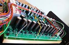
PMA said:Hereby the functional sample:
Teflon is heavy and has high inner damping, and is also nice and easy to work with.
Teflon does nothing for shielding.
Shielding I do with GND planes, and conductive boxes.
Some use u-metal for magnetic field shielding but I have
not tried that.
Sigurd
Teflon does nothing for shielding.
Shielding I do with GND planes, and conductive boxes.
Some use u-metal for magnetic field shielding but I have
not tried that.
Sigurd
Onvinyl said:Hi Sigurd,
what exactly does Teflon against vibrations and for shielding?
thanks,
Rüdiger
Thanks, but it is just a routine sample/prototype.
Yes, I have simulated and measured the noise 😉 .
Yes, I have simulated and measured the noise 😉 .
Re: Rumble filter
15 kilo .. woow that is heavy-tungt
I had 2 ideas, myself, after I had put the question to Charles Hansen, the Ayre constructor.
1. A very well dimensioned Power Supply Trafo. To get close to an ideal supply.
MC RIAA amplifiers, in particular, are a bit kinky and demanding when comes to sofisticated and Clean supply of currents.
2. Vibrations. Now the turnatable is of course sensitive to this.
But it is not that easy to understand how MC phono amplifier can suffer from vibrations.
So, thanks PMA and Sigurd for your answers.
This did clarify several things, for me and I hope for others.
-----------------------
Finally, I respect you both.
I have seen & read at forum, and know how much knowledge you possess. And neither of you will very often sink to low level posts. And get too personal. And there is nothing to gain, whatsoever, to confuse subject with person.
Many times is better to just simple couragously, honestly admit,
as a real Gentleman would:
🙂
lineup - friendly hifi regards
Vilken härlig dag. Man blir härligt glad.
Allting börjar knoppas. Man kan börja hoppas, det blir vår i år!
PMA said:I can imagine well protecting housing (against EMI), that would make the MC preamp pretty heavy.
Sigurd Ruschkow said:I do not care about weight much. What I do care about is that an MC RIAA amp should be sturdy and also take care of vibrations, and as PMA wrote, very good shielding is important.
So, I use Teflon PCB when I can, and a large Teflon plate under this PCB. PCB is hung in rubber stand-offs.
The raw power supply with its transformers is in another box than the MC amplifier.
This setup will make an MC RIAA at about 15 kg.
Sigurd
15 kilo .. woow
that is heavy-tungtI had 2 ideas, myself, after I had put the question to Charles Hansen, the Ayre constructor.
1. A very well dimensioned Power Supply Trafo. To get close to an ideal supply.
MC RIAA amplifiers, in particular, are a bit kinky and demanding when comes to sofisticated and Clean supply of currents.
2. Vibrations. Now the turnatable is of course sensitive to this.
But it is not that easy to understand how MC phono amplifier can suffer from vibrations.
So, thanks PMA and Sigurd for your answers.
This did clarify several things, for me and I hope for others.
-----------------------
Finally, I respect you both.
I have seen & read at forum, and know how much knowledge you possess. And neither of you will very often sink to low level posts. And get too personal. And there is nothing to gain, whatsoever, to confuse subject with person.
Many times is better to just simple couragously, honestly admit,
as a real Gentleman would:
You were right.
I cant argue no more.
Let's move on, fellow audio comrade.
It is a bit foolish to me, go on defend a lost case and argue in vain.
There is no way you will be able to cover this from topic readers.
And so you can even end up being laughed about.
People will resort to many things, when they can not defend their opinion, their StandPoint.
Unfortunately.
🙂
lineup - friendly hifi regards
Vilken härlig dag. Man blir härligt glad.
Allting börjar knoppas. Man kan börja hoppas, det blir vår i år!
🙂
Of course you have....
As you can guess, I am interested in knowing the result.
Especially now when you tell us that you have BOTH simulated AND measured noise for your RIAA amp. Then we can compare the hard world from the soft world.
Most interesting would be a total noise rms Voltage from 20 - 20 kHz.
Simulating THD I know you do well, too. Have you compared simulated and measured values, and if so, what did you find?
Sigurd
PMA said:Thanks, but it is just a routine sample/prototype.
Yes, I have simulated and measured the noise 😉 .
But it is not that easy to understand how MC phono amplifier can suffer from vibrations.
Really? You can come up with a number of mechanisms that could have an effect. Speaking of phono stages , NAIM audio, just as an example, just brought out a pretty new phono stage that has the circuitry mounted on a heavy brass sub-chassis. To what extend (if any) the difference is audible I cannot tell, but for a diy design I don't see why you could not try this method.
A bit of a spaghetti amp though, but likely unavoidable with a dozen regulator stages per channel and a spring/subchassis suspension.
My current phono-pre has the shunt stages of the V-regulators on the board, making the PCB + components on it weigh in at +4lbs, which reduces the need for substantial subchassis mass.
With the solid alloy case added, also in the +32lbs total weight range.
Pretty amazing actually that a company as NAD can keep the weight of their C-note PP2 vehicle down to 1 pound only.
Compared to the likes of a BUF or the Hitachi final stages of a Curl Vendetta, the output buffer in the posted schematics look rather squeemish.
(hihi, Tino is hooked on an Elektor clone, Mr MATsula)
Attachments

Here is a more conservative input stage with riaa that won't destroy any cart. The servo opamp is indicative and chosen here because of ease of implementation in LTSpice, I would chose AD820, OPA134 or OPA627.
All runs from +/- 12V rails.
THD is non-exsistent, output noise in the chosen band is 1.8µV/rtHz (where full output swing @1k is 20mV) so a bit highish for this foruims standards, but probably buried under surface noise during playback.
1k gain is 26dB, so another 30 - 40dB gain stage must follow.
The FETs I have are between 7-8mA IDSS, so they bias around 6mA each here. The quality of Q5/Q6 seem crucial, differnt types give quite different performance.
I will eventually build and compare it with my cart destroyer circuits.
Rüdiger
Attachments
You would need about 34dB/1kHz added gain for most MC cartridges, 300uV/cms-1 is usual sensitivity.
Edit: you told that, sorry.
Edit: you told that, sorry.
My current phono-pre has the shunt stages of the V-regulators on the board
What, no cap multipliers after the V-regs

the PCB + components on it weigh in at +4lbs, which reduces the need for substantial subchassis mass. With the solid alloy case added, also in the +32lbs total weight range.
Sounds actually like an optimal basis to put in a subchassis.
Btw., Mr. Hansen … ehhmm, sorry, Mr. Ingo Hansen of Phonosphie here in Germany claims the more mass a cabinet has the more vibrational energy it actually stores and that his component chassis made of 4mm aluminium sheets are optimised: "In contrast to the heavy armour wrapped around common high end audio components, it will not suffer from vibration energy trapped …". Not sure if in his case (no pun intended) this is pure marketing BS but just adding mass may be too simple?
Onvinyl said:Here is a more conservative input stage with riaa that won't destroy any cart. The servo opamp is indicative and chosen here because of ease of implementation in LTSpice, I would chose AD820, OPA134 or OPA627.
All runs from +/- 12V rails.
THD is non-exsistent, output noise in the chosen band is 1.8µV/rtHz (where full output swing @1k is 20mV) so a bit highish for this foruims standards, but probably buried under surface noise during playback.
1k gain is 26dB, so another 30 - 40dB gain stage must follow.
The FETs I have are between 7-8mA IDSS, so they bias around 6mA each here. The quality of Q5/Q6 seem crucial, differnt types give quite different performance.
I will eventually build and compare it with my cart destroyer circuits.
Rüdiger
Thanks, Onvinyl.
Something like that, I will try to setup in my spice.
We can go several ways here, if we omit Input cap, which the knowing think we shoud.
1. Provide AC and DC global feedback combined
2. Provide AC and DC global feedback. Separate, like your Opamp based servo
3. Provide DC feedback only. No global AC FB, like Charles Hansen in Ayre expensive RIAA amp.
4. No FB. Try to make a linear amplifier. Use output capacitor of high quality, like Pass Labs Pearl Phono.
What we use is much a matter of taste. There are many roads, but they will go to Rome in Italy!
I would use a method that I like and feel good about:
Provide lower level AC feedback + use a good Audio Capacitor, polypropylen, at output of stage.
How much gain should be in first stage for MC RIAA?
We know that some pickups deliver only like 0.5-1.0 mV peak in audioband and maybe lower than this.
??? What input level do we need to feed the other stages?
+26dB as in your circuit means gain x20.
lineup friendly hifi regards from the north
Lineup said:
2. Vibrations. Now the turnatable is of course sensitive to this.
But it is not that easy to understand how MC phono amplifier can suffer from vibrations.
You quote me MRupp, and you say:
You can come up with a number of mechanisms
that could have an effect.
---------------------------------------------------------
'A number of mechanisms'
Please tell us, MRupp.
I guess there are several more readers than me, that still are a bit in the wonder how this works, physically.
🙂
My audio intiution tells me that vibrations may very well effect a low level high gain audio amplifier. Many vibrations, if not most, has got a frequency within the audio band. But the exact physical mechnism of how semiconductors/passive components are electrically influenced by vibrations, is not 100% clear to me.
- Has there been any research on this?
- Somthing else published, tests etc. especially regarding audio?
lineup hifi regards
Rudiger,
Do you think it would help to cascode the j-fets because of capacitance of the j-fets?
Jam
Do you think it would help to cascode the j-fets because of capacitance of the j-fets?
Jam
Hi lineup,
I would avoid caps at least between stages, but prefer to no caps at all.
Regarding AC feedback: I would avoid it if I could. I have a open loop 2x4 FET input stage followed by a folded cascode, but for optimum performance I'd need over 50mA current in the fc device. That's a bit unsane. Gain isn't sufficient, too.
The Rabeyrolles-style input stage I'm currently using has no AC FB-loop the way I use it and sounds great, but has that potential input offest issue.
Rüdiger
- Status
- Not open for further replies.
- Home
- Source & Line
- Analogue Source
- Solid state phono preamp design philosophy