1. You're right. It can be substantially less than 3W and smaller as a result. (I had checked R1 and R3 but never R2.)
2. Fair enough. I would, however, struggle to claim it as my design. I took the store's circuit and made modifications to replace the resistor bank with an NTC plus other modifications kindly suggested by you. I very much appreciate all the tuition/guidance.
I've also modified the labeling of the mains contacts so that it can be seen when an insulated Faston has been attached and to be label the outbound versus return switch contacts.
Check the voltage limit of your resistor.
Some/many will not stand 240Vac.
Better/safer to use a series pair, or even a series triple.
Some/many will not stand 240Vac.
Better/safer to use a series pair, or even a series triple.
Table1 is not identified but I presume they mean that the 1/2W resistors have a maximum working voltage rating (WV) of 350V, the quoted para implies to me that they actually mean 350Vac, but have written 350V, which usually means DC, or peak in that context.Dielectric withstanding voltage - No evidence of flashover mechanical damage,arcing or insulation break down. - 5.7 Resistors shall be clamped in the trough of a 90° metallic V-block and shall be tested
at AC potential respectively specified in the
table 1
Due to mains interference, the nominal mains Vac is not the maximum voltage applied to the resistor. It is Vpk (~358Vpk) plus the interference spike which can be as high as 1500Vpk.
I would NOT use a single resistor to withstand 240Vac + mains interference nearly permanently.
I would look at using two or three in series, because that document leaves me in doubt since it does not mention interference during the no flash over test.
Last edited:
More suitable? Even at 125C continuous working voltage of ~358V peak is inside SQRT(PWR rating x R). Not the cheapest to select...
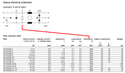
Then you don't want to apply for a job at Schaffner, making powerline EMI suppression filters. They use a single resistor across the 240VAC mains.I would NOT use a single resistor to withstand 240Vac + mains interference nearly permanently. ... I would look at using two or three in series ...
(Here is one of their representative products, with a link to its datasheet), and I've attached a couple of relevant portions, below.

Attachments
Maybe ask the valve amplifier hobbyists and pros on this website, what types of resistors they use for >500 volt applications? It must be a Solved Problem by now.
Or just look for inexpensive, current production resistors with high voltage ratings. The Vishay "HVR25" series appears to fit the bill: (Here they are on UK Mouser's website), selling a 1Megohm resistor with 1600 volt rating, for £0.329 . I presume Vishay's competitors have products on offer, at comparable or possibly lower prices.
Or just look for inexpensive, current production resistors with high voltage ratings. The Vishay "HVR25" series appears to fit the bill: (Here they are on UK Mouser's website), selling a 1Megohm resistor with 1600 volt rating, for £0.329 . I presume Vishay's competitors have products on offer, at comparable or possibly lower prices.
Thanks Mark. Andrew, I'm not sure what post you are responding to.
The original circuit called for a metal oxide resistor. I had searched within this resistor type. Are there special considerations in this type of application that drive/necessitate a particular type of resistor?
The original circuit called for a metal oxide resistor. I had searched within this resistor type. Are there special considerations in this type of application that drive/necessitate a particular type of resistor?
Last edited:
If you are able to find a Mains rated resistor that is guaranteed to safely survive interference spikes, then use it. They will exist.
In the absence of finding such a safe device, then series connected resistors of a lower safety rating can be made to work adequately well. But take care with creepage distances/gaps.
In the absence of finding such a safe device, then series connected resistors of a lower safety rating can be made to work adequately well. But take care with creepage distances/gaps.
I suppose it might be useful to decide whether the equipment will contain one of THESE and/or perhaps one of THOSE -- correctly positioned with respect to the EMI filter and fuse, of course. If so, it provides an upper bound upon anomalous conditions that might possibly occur.
Personally, I prefer to connect my equipment to the mains using this somewhat costly technology. It is covered by several patents, the first of which seems to be US 4,870,528. But other hobbyists naturally have their own preferences.
Personally, I prefer to connect my equipment to the mains using this somewhat costly technology. It is covered by several patents, the first of which seems to be US 4,870,528. But other hobbyists naturally have their own preferences.
Last edited:
Then "interference spikes" on the mains will be attenuated before they arrive at your equipment; the worst case stress upon your resistor-across-the-mains will be considerably smaller.My equipment is plugged into an Isotek GII Titan. The newer version is listed here.
Cheers. This version has been sent to SeeedStudio. I keep working on my other stuff. (I've integrated the soft start model into my overall model of the three voltage rails etc. Need to iron out some issues there before doing any more board work.)
One somewhat generic question: the footprint on the board for C2 is 13x32mm. The EPCOS 1uF cap suggested by Mark is 11x31.5mm. Its 1.5uF brother is 12.5x31.5mm. Their 2.2uF brother is 15x31.5mm. The latter could fit were it not for the fact that the casing would get very close to, if not touch/overlap, the pad for D5. Would that be a bad thing - my presumption is the case isn't conductive and so, while perhaps a little untidy, it wouldn't be a problem...(he says rather meekly)
One somewhat generic question: the footprint on the board for C2 is 13x32mm. The EPCOS 1uF cap suggested by Mark is 11x31.5mm. Its 1.5uF brother is 12.5x31.5mm. Their 2.2uF brother is 15x31.5mm. The latter could fit were it not for the fact that the casing would get very close to, if not touch/overlap, the pad for D5. Would that be a bad thing - my presumption is the case isn't conductive and so, while perhaps a little untidy, it wouldn't be a problem...(he says rather meekly)
Attachments

Rotate the pads for D5, put their long axis perpendicular to the diode body.
Or, move C2 upward by two grid-squares. If necessary, move NTC to the right a couple of squares.
Or, move C2 upward by two grid-squares. If necessary, move NTC to the right a couple of squares.
Yes I could change the board layout to accommodate the larger cap. My question, though, was more as regards what's possible "as is" because
😉
1.5uF for C2 and 7.5k for R3 (with UK voltages) results in the bypass kicking in after about 320ms. I realised that for my specific application I could have it kick in even sooner. It's not the end of the world if it doesn't but my rail voltages, as currently profiled, can't come up to their max 5A load with the NTC in the loop and the NTC needn't be in the loop for longer than about 150ms. I likely couldn't turn on the rear panel switch then the front one within 320ms anyway and I very much doubt the load will be so high so quickly either. Of course I could also reconfigure the softstart to delay front-panel power-on until after the by-pass kicks in but I wanted this soft-start module to be more generic and potentially of use to others.
If I do another version I will surely accommodate the slightly wider cap.
This version has been sent to Seeedstudio.
😉
1.5uF for C2 and 7.5k for R3 (with UK voltages) results in the bypass kicking in after about 320ms. I realised that for my specific application I could have it kick in even sooner. It's not the end of the world if it doesn't but my rail voltages, as currently profiled, can't come up to their max 5A load with the NTC in the loop and the NTC needn't be in the loop for longer than about 150ms. I likely couldn't turn on the rear panel switch then the front one within 320ms anyway and I very much doubt the load will be so high so quickly either. Of course I could also reconfigure the softstart to delay front-panel power-on until after the by-pass kicks in but I wanted this soft-start module to be more generic and potentially of use to others.
If I do another version I will surely accommodate the slightly wider cap.
It's best practice to usually have all diodes (also applies to polarized caps), to have their polarities all oriented in the same direction. Less chance of mistakes happening when manually populating them.
You can rotate D2 and D3 180-degrees.
Personally, I like (+) to be on top, so C3 can be rotated too. - but that's my personal preference.
You can rotate D2 and D3 180-degrees.
Personally, I like (+) to be on top, so C3 can be rotated too. - but that's my personal preference.
** MMMmmmm.... The bottom layer copper by the relay seems to be touching (or very close to) the (3) relay pads.This version has been sent to Seeedstudio.
Last edited:
I suspect that the majority of people who want soft-start, will use it on equipment whose long term average current drawn from the mains (when playing music loudly) is higher than 5 amps. I suspect these people will need/want super high current relay contact ratings, which means either buying SPST relays, or connecting a DPDT relay's pair of contacts in parallel. Us poor devils in the States, who need twice the current just to get the same power (thanks to half the mains voltage), will be leading the charge.
So I suspect that DPDT_relay_gives_softstart_with_hysteresis deployments , will remain a small minority. Too bad, it's useful and cute.
So I suspect that DPDT_relay_gives_softstart_with_hysteresis deployments , will remain a small minority. Too bad, it's useful and cute.
- Home
- Amplifiers
- Power Supplies
- Soft start circuit design and other psu issues