In discussions about Voltage slew rates this refers to the VAS which is different from Output stage current slew rate which depends on the base currents available to turn transistors off on opposite half cycles in a switching amplifier - i.e. Class B.
Push pull Class A systems can move from Class A towards Class B depending on how hard these are pushed - for instance into a low impedance load so it would be unwise to skimp too much with the calculations.
For more information on the latter I suggest you read the article in Bob Cordell's papers at http://www.cordellaudio.com/papers/another_view_of_tim_II.pdf
You would do well to also read part one that precedes this article.
Thank God I don't have to! Ltspice does it for me!
Slew rate is defined as V/us, but you have no damn slew rate if you can't push your current through the damn 2...8 ohm INDUCTIVE load.
You could have a billion V/femto second in the op amp...if the final stage can't deliver it to the load you have 0V / 1 billion years slew rate.Try listen BA 5218 on headphones and you'll see what a 2...3v/us op amp can do just because it can deliver enough current to the load.There's no slew rate without the ability to push a current through a load and no op amp can do that on 8 ohms that is why you have a buffer...the op-amp itself has an internsl buffer too.Why are you biasing for class A to make 20khz crossover distortion as low as possible and why are you looking for low cob transistors in the final stage when you could just use your billion volt slew rate op-amp and you're done...!?
As for slew rate requirements of an amp...now that it's clear you're the true engineer here, maybe you could tell me how a 9v/us vfb op amp can drive a qsc1700 with 21 v/us at 600 watts of power into 4 ohms if only the input ltp of ne5532 is the one responsible with slew rate and basically you can only go down below 9v/us with any added compensation, not up...Apparently there's no need for more than 21V/us either ...
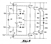

Except there's no thermal compensation in PMA design...and the input is common base derived from old Bloomley and Hartsuiker designs that allows for minimal compensation and op-amp drive.Nothing really new under the SUN ...but we can enjoy expired patents...I certainly do, it's called universal herritage 🙂Kind of resembles Figure 5 of US Patent # 3,995,228 issued to Nelson S. Pass on 30 Nov 1976.
_
.
As far as a lack thermal compensation goes consider that a different function of Q1 and Q2 when T1 and T2 heat up and pass more standing current through their emitter resistors.Except there's no thermal compensation in PMA design...and the input is common base derived from old Bloomley and Hartsuiker designs that allows for minimal compensation and op-amp drive.Nothing really new under the SUN ...but we can enjoy expired patents...I certainly do, it's called universal herritage 🙂
.
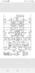
The triple output stage is biased by constant current structures so any current stolen away from these sources by Q1 and Q2 restricting the input current fed to the triple stage will reduce the output standing current. That should be enough but if heat becomes too much of a problem because of limited heat sink arrangements and hotter climates, a thermal cut out with normally open contacts, connected across the bases of Q3 and Q4 could be a useful back up
Last edited:
As there has been a usual pell-mell of output stages suggested in this thread, I am not sure if the last remarks on thermal stability are related to the subject of this thread (post #1) 😉. If yes, then I may make you sure that the resulting temperature coefficient of the amplifier is slightly negative and even the longterm, continuous operation with heatsink smaller than required does not lead to thermal runaway.
Commercial professional amplifiers have all the protections at all time.You can't really prevent thermal runnaway inside a triplet ccs.And this amp in particular is hot in any season and climate being class A.I think this technique is called prevention...As far as a lack thermal compensation goes consider that a different function of Q1 and Q2 when T1 and T2 heat up and pass more standing current through their emitter resistors.
The triple output stage is biased by constant current structures so any current stolen away from these sources by Q1 and Q2 restricting the input current fed to the triple stage will reduce the output standing current. That should be enough but if heat becomes too much of a problem because of limited heat sink arrangements and hotter climates, a thermal cut out with normally open contacts, connected across the bases of Q3 and Q4 could be a useful back up
Attachments

Commercial professional amplifiers have all the protections at all time.You can't really prevent thermal runnaway inside a triplet ccs.And this amp in particular is hot in any season and climate being class A.I think this technique is called prevention...
Yes. 1st, this is not a "commercial amplifier". 2nd, the real amplifier has been here since 2016
https://pmacura.cz/pma4_en.htm
and 6 years is quite enough to tell about reliability and function in any season. Though you are just guessing, I am talking based on real life, measurements and experience.
You are saying that hopefully you have a LTSpice, I am saying I have it too and that simulation is the only first small, very small step. Armchair design is not my goal, I know how little it means.
The main purpose of the thread is to show how low distortion is achieved.
Q1,q2 are cool on the pcb...on a 3.4 mA leash...Can they shorten the triplet input ? Probably...What happens if q5/q6 get shorted CE? At least we know that for the moment Poland is cool.
Armchair design...How's your spider veins doing?
Armchair design...How's your spider veins doing?
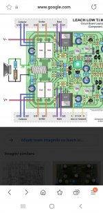
The same applied to the Leach Low TIM amplifier I built over 30 years ago . This too had an output triple output stage.As there has been a usual pell-mell of output stages suggested in this thread, I am not sure if the last remarks on thermal stability are related to the subject of this thread (post #1) 😉. If yes, then I may make you sure that the resulting temperature coefficient of the amplifier is slightly negative and even the longterm, continuous operation with heatsink smaller than required does not lead to thermal runaway.
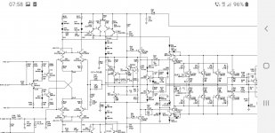
You mean this Leach amp?The same applied to the Leach Low TIM amplifier I built over 30 years ago . This too had an output triple output stage.
Attachments

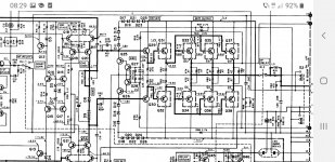
If say T1 and or T2 fail short circuit R11 and R12 , which look from the photo in post to be 0.6 W rated, I can't make out the colours well enough to determine the resistance, but these would be likely for these to burn out and prevent Q5 and Q6 from being damaged. In a commercial design these could be fusible resistors that don't flame out. Sometimes low wattage resistors can burn out from the inside and not have visible signs on the outer surface.Q1,q2 are cool on the pcb...on a 3.4 mA leash...Can they shorten the triplet input ? Probably...What happens if q5/q6 get shorted CE? At least we know that for the moment Poland is cool.
Armchair design...How's your spider veins doing?
Do you have any more objections to this circuit or is it time to let the thread move ahead.
Of course there are ways to get out of any unknown situation. I met internally fried fusible resistors in a few cases, but I can't remember being so happy about it cause it took me a full day to guess some 1/4th watt 220 kohms in a VFD motor controller.It seemed like the least possible damage and yet it happened .
Repair and fixes are my best skills for 2 decades unlike armchair designs, not going to brag about it though... Will adding some diodes degrade the performance of this amp? I doubt that. Will substracting them make this an original fully functional protected amp ? Maybe NP would be the first one to have a say on this, but he's obviously occupied with better things to do...I'm gonna follow his example myself.
Have a good day!
You are keep repeating how use of spice (LTsice) is just very small step to design power amp, but I disagree with you. With good semiconductor models you can do more then 50%(even 80%) of an electronic design including power amps.You are saying that hopefully you have a LTSpice, I am saying I have it too and that simulation is the only first small, very small step. Armchair design is not my goal, I know how little it means.
I built some of mine power and pre amps and practically had to change very little in the build and testing phase, mostly protection part.
Mine is the first incarnation from Audio magazine February 1976 with updates from February 1977. I passed on the next update in 1978 as the changes meant disassembly and incorporation of the old components with a couple of extra transistors on a new pcb. A friend acquired a later version which had a fault that I resolved and his amp sounded better than mine. It could have been the computer grade caps he used for power supplies. I could have written away to get updated boards however I had done that with an updated version of the Leach pre-amp enclosing a money order simply for the layout and waited and waited but these never arrived.You mean this Leach amp?
Last edited:
By the way...all those 0.00000x thd will hit a wall made by a real speaker moving real air having real back emf...
Attachments

We all know that 🙂. It is just a hobby, kind of a sport, finding possible and impossible. Our amplifiers are in 3 - 4 orders better than speakers, talking about distortion.By the way...all those 0.00000x thd will hit a wall made by a real speaker moving real air having real back emf...
If you can design very low THD amplifier why you don't make it? You will know the sound after you make it. It shame for people that can not design such amplifier and even NEVER used and hear such amplifier, but criticized it.We all know that 🙂. It is just a hobby, kind of a sport, finding possible and impossible. Our amplifiers are in 3 - 4 orders better than speakers, talking about distortion.
- Home
- Amplifiers
- Solid State
- Small class A amplifier with THD below 0.0001%