The output stage uses local NFB and has vanishingly low distortion below 0.001% itself
Which is the local NFB ? Emitter resistors ?
How about a resistor in parallel with c3?This is the complete schematics with part numbers. IC1 supply voltage is to be adjusted by R22/R23 and R20/R21 between 18-20V, according to the opamp used. LT1122 tolerates up to +/-20V according to the datasheet. OPA637 max. supply is +/-18V. I run it at +/-19V, which exceeds parameters specs, but it works so far.
Idle current is 1.5A and is measured as a voltage across R14 and R15. Voltage across emitter resistors is used for a local NFB via Q1 and Q2.
C19 and C20 reduce HF distortion and improve HF linearity considerably by reducing rail modulation by input signal.
To achieve large S/N at mains frequency and multiples great care must be taken in signal GND track routing. Small signal GND to be routed separately and connected with large current GND at the point LSP7 where PSU 0V terminal is soldered into PCB. The difference in mains residual can be as large as 30-40dB if the small signal GND is routed improperly. This and rail modulation by input signal is difficult to see from simulation only.
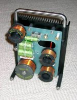
Idle power dissipation is about 75W per channel. An appropriate heatsink with low thermal resistance must be used. The one shown in my sample photo is insufficient for normal operation. I was using 19" 3U case with side heatsinks with fins and low thermal resistance during the normal listening operation of the amp.
Ive seen a similar amp with such feedback arrangement and wonder what its effect is
Edit: resistor value 15k
I remember vaguely reading a report from you some years ago, showing the step responese of a power amp with 1µF at the output.
I wonder if you have a "standard" stability test, and if yes, whether you would kindly share.
Thx,
Patrick
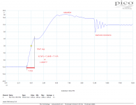
The step/square response into 4ohm//1uF is quite a cruel test, but you may have it.

Voltage seen across R14, R15 fed back through R7, R8 to base of Q1, Q2 driving Q1 and Q2 to control output stage input at base of Q3, Q4.Which is the local NFB ? Emitter resistors ?
How about a resistor in parallel with c3?
Ive seen a similar amp with such feedback arrangement and wonder what its effect is
Edit: resistor value 15k
The parts like C3 with zero value (in the latest schematics) are unused and positions on PCB are prepared for eventual use.
This step test into R//1uF is IMO pointless. In ideal case, with ideal step, the capacitor would eat infinite current, because Ic = C . (dv/dt) and for dt = 0 Ic is infinite. This test in fact reflects parasitic impedances of the circuit (lead wire inductances, capacitor ESR and ESL). And, if we have troubles with instability into capacitive load, we usually see it with load capacitance between 5nF and 100nF, rather than with 1uF. With 1uF, we can see parasitic impedances as mentioned and amplifier's output current limit. I tried to decipher the plot, but is is just one possible view. Many amps will go into current protection and some amps will be destroyed by this test.
Attachments
So what is a reasonable test in your opinion ?
Do you design your open loop response with pure resistive load, and just allow x amount of phase / gain margins ?
Patrick
Do you design your open loop response with pure resistive load, and just allow x amount of phase / gain margins ?
Patrick
Merci beaucoup
This schematic is a very interesting .. many things to look at ... I will be glad to study it ....
This schematic is a very interesting .. many things to look at ... I will be glad to study it ....
Looks like a composite amplifier. An inverting current feedback amplifier inside of the voltage feedback amplifier closed loop.
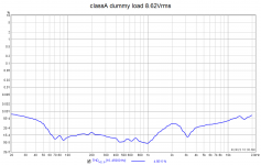
Capacitive loading is fine to test from 100pF to 100nF. You might be surprised but the worst load is coaxial speaker cable with length >5m with open end. Impedance is violent above 1MHz with dips where capacitive component goes in uF order. Many amps get to oscillations with such load. I always use a complex speaker dummy load with nonlinear inductance to check both amplifier FR and distortion with it.So what is a reasonable test in your opinion ?
Do you design your open loop response with pure resistive load, and just allow x amount of phase / gain margins ?
Patrick
This is what I use. But not sure if it is severe enough test.
https://www.stereophile.com/content/real-life-measurements-page-2
https://www.diyaudio.com/community/...se-for-a-simple-cheap-load.91479/post-1073195
Patrick
https://www.stereophile.com/content/real-life-measurements-page-2
https://www.diyaudio.com/community/...se-for-a-simple-cheap-load.91479/post-1073195
Patrick
Attachments
It is good. I have a very similar dummy load circuit.This is what I use. But not sure if it is severe enough test.
A minute ago I have finished testing of THD vs. power and THD vs. frequency with 4ohm//1uF load. There is almost no difference compared to 4ohm pure.
More interesting is the change of opamps. Below is OPA627xOPA637. OPA637 gives the best results by far, in this circuit. Followed by LT1122 and then OPA627. OPA134 has higher HF distortion than OPA627. BJT input opamps are unusable in this circuit, it needs low input bias current. Attached is also the result with dummy load. My dummy load has highly nonlinear 18mH ferrite core inductor which simulates quite well speaker nonlinear impedance.
Attachments
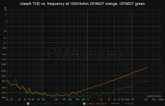
You get some 12dB more OLG with OPA637.
So no surprises.
I wonder hoow ADA4637 would compare.
Patrick
So no surprises.
I wonder hoow ADA4637 would compare.
Patrick
Yes OPA637 is a very fine opamp, sadly the DIP-8 packages of OPA627/637 have recently been listed as EOL. I would stock up on them, but considering their price that isn't really an option. I don't know how happy OPA827 or OPA828 would be on an adapter PCB, but maybe those are worth a try as well?
@PMA: Did you order your PCBs from Aisler? The finish somehow looks very familiar. If so: Any chance you can send me a share link to order a set?
@PMA: Did you order your PCBs from Aisler? The finish somehow looks very familiar. If so: Any chance you can send me a share link to order a set?
No, the PCB was produced in 2016 by a local PCB manufacturer in Prague. Recently I am sometimes ordering PCBs from PCBWay China. Regarding the kit, I am sorry but I stopped selling kits and PCBs in 2012. Maybe I will start some sales later, but it is just undecided.@PMA: Did you order your PCBs from Aisler? The finish somehow looks very familiar. If so: Any chance you can send me a share link to order a set?
You get some 12dB more OLG with OPA637.
So no surprises.
I wonder hoow ADA4637 would compare.
Patrick
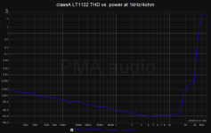
Hi Patrick, some opamps may surprise us. One of them is LT1122 which fits perfectly to this design and has supply voltage up to +/-20V. I guess that the old datasheet measurements of distortion were made with not enough resolution and were not updated.
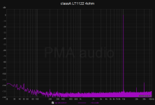
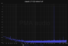
Below are measurements with LT1122. THD(power) into 4ohm at 1kHz - see the transition into class AB at 18W and then still 30W with 0.004% distortion. Also added are measurements at 10kHz into 4ohm resistor and 4ohm//1uF capacitor.
Attachments
Last edited:
Yeah, nice to see this.I always use a complex speaker dummy load with nonlinear inductance to check both amplifier FR and distortion with it.
Also, thanks for sharing your design and test results.
No, the PCB was produced in 2016 by a local PCB manufacturer in Prague. Recently I am sometimes ordering PCBs from PCBWay China. Regarding the kit, I am sorry but I stopped selling kits and PCBs in 2012. Maybe I will start some sales later, but it is just undecided.
Ah yes, my brain skipped the part of your original post where you mentioned that it was an old project of yours. I still find the OPS interesting, I will move parts of it to SMD and give it a try.
Please do not forget to use a big heatsink for output transistors and drivers with thermal resistance <0.4°C/W, idle dissipation is about 70W.I will move parts of it to SMD and give it a try.
Also added are measurements at 10kHz into 4ohm resistor and 4ohm//1uF capacitor.
Probably these tests with 4R//1uF load may make some sense.
https://www.stereophile.com/content/sound-lab-1-electrostatic-loudspeaker-measurements
- Home
- Amplifiers
- Solid State
- Small class A amplifier with THD below 0.0001%