Thanks Jason.
I was leaning towards those but was also thinking the 21194/93 because though they are less voltage, they have higher amp rating. ...
Blessings, Terry
Terry,
I just pulled up the data sheets and have to retract my suggestion and say for maximum safe operating area to go for the MJL21193/MJL21194 with any suffix. My memory was faulty, my apologies.
Something to remember though it is not the overall amperage rating, but rather the amperage rating at some higher voltage. On a data sheet you will usually find a graph showing 'Safe Operating Area'. Look at the amount of current the device is allowed at say 100V and you will find some hefty sounding devices fall off really fast once the voltage rises, especially many older types.
MJL4281/MJL4202 > 1A@100V for 1s
MJL21193/MJL21194 > almost 2A@100V for 1s
So, the 21193 and 21194 offer almost twice the allowable current at 100V across them which means there is substantially more 'Safe Operating Area' available.
4R and 2R drivers + low rails ...
Speaking of SOA , My new sub is subjected to over 200W with just
3 pair of tiny NJW's.
<50V rails is over double the SOA for these devices.
I wonder whether it is better (or louder) to divide the audio spectrum
in 2 ( <100hz and 100-20k) or to run massive rails fullrange ?
I'm cooler , louder , and more efficient with my current 2.1 system than
when I was running 72V rails on my first 4 pair OP / fullrange setup
when i joined the forum ("supersym" 2008-9) !
OS
Hi Jason,
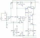
Thanks, that's why I asked. I have learned another tidbit. I have another question. While waiting for the new boards I spent some time and populated the front half of my Symasym boards. I am attaching the schematic. My question is how to set the output. I assume it needs the same 4.5-5ma as the CFA. Where would I measure and how would I adjust if it is not in the proper range?
Thanks, Terry
Attachments
Then leaving the volume pot alone I began graduating the frequency upwards and simply changed the time dial on the scope. The relative height of the square wave on the screen stayed the same but the voltage reading on the DMM began to drop when I reached the higher frequencies. At 100khz I tried raising the level some while watching the DMM and then noticed smoke rising from the zobel. I wouldn't be surprised if there were no zobel resistor to reveal that, an output would be the next thing damaged.
Hi, not all mutimeters are accurate when Measuring AC at high frequencies,
Trust the level on your scope and not the reading on your DMM.
Maybe by going on the reading of your DMM (which might be totally incorrect reading when measuring AC at higher frequencies) you adjusted the level much higher than the meter was indicating.
Zobels WILL smoke when the amp is driven Hard with High frequency square waves.
Regards
Last edited:
Hi Jason,
Thanks, that's why I asked. I have learned another tidbit. I have another question. While waiting for the new boards I spent some time and populated the front half of my Symasym boards. I am attaching the schematic. My question is how to set the output. I assume it needs the same 4.5-5ma as the CFA. Where would I measure and how would I adjust if it is not in the proper range?
Thanks, Terry
Terry,
I'm not 100% sure since I personally have not worked with the Sysasym, but based on your diagram it looks like the 68Ω resistor that forms the VAS 'tail' will be the one to increase / decrease should the current not be in the desired range. We do want all our IPS to run in the same range of current.
Hi Jason,
Thanks for taking the time to help. I have a couple more questions if I may. I'm still trying to learn something here.
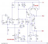
OS had suggested changing R10 from 68R to 150R. I am assuming this is to reduce the VAS current. I'm wondering if I can use maybe a resistor in parallel with a pot for R10 so I could adjust it and then measure what I have and install that size resistor. Can I measure across R18 (47K) to determine the VAS current?
OS also recommended changing R11 from 220R to 270-470R. I am assuming that is to reduce the current in the LTP. Same question here. Can I install a pot temporarily so I can find the best value?
I am attaching a more accurate schematic showing the LTP emitter resistors that are actually in the circuit.
Thanks, Terry
Attachments
Terry
Imagine that you have two stretchy ropes as per picture bellow.
Brown - input bias
Red - VAS bias
If you are pulling brown rope ---> you are ''pulling'' red rope too.
Both ropes are connected and if R11 is 270R (instead 220R) you are pulling it less hard than also you pulling less hard red rope (vas).
What happend if you are pulling brown one too light --> red one is not pulled at all.
R11=270R
IPS-->2.5mA
VAS-->3.7mA
R11=220R
IPS-->3mA
VAS-->6.8mA
So only by changing R11 you are changing the vas current.
Attachments
Hi Borys,
That is very interesting. Thanks for the detailed explanation. I have been reading back through the Original Symasym thread trying to determine what MikeB suggested for a good bias point for the LTP but I have not found it yet. OS suggests 4.5mA for the VAS in order to match up well with the OPS. If I am understanding you correctly, changing the LTP current will also affect the VAS current so am I correct that the LTP current need to be adjusted first and then the VAS? Do you have an idea of what the LTP should be set to? Looks like both examples you provided result in either too low or too high an output.
Thanks, Terry
Hi Jason,
Thanks for taking the time to help. I have a couple more questions if I may. I'm still trying to learn something here.
OS had suggested changing R10 from 68R to 150R. I am assuming this is to reduce the VAS current. I'm wondering if I can use maybe a resistor in parallel with a pot for R10 so I could adjust it and then measure what I have and install that size resistor. Can I measure across R18 (47K) to determine the VAS current?
OS also recommended changing R11 from 220R to 270-470R. I am assuming that is to reduce the current in the LTP. Same question here. Can I install a pot temporarily so I can find the best value?
I am attaching a more accurate schematic showing the LTP emitter resistors that are actually in the circuit.
Thanks, Terry
This looks like one design that needs a holistic approach to re-tuning, I don't think it is as easy as just changing a value or two. Certainly can be done and re-purposed with a little care.
The input LTP tail current is set by R11 and the VAS current is partially set by R10 but the VAS current also depends on the input LTP current - there is dependancy, the VAS current depends on the LTP current. The input LTP is loaded resistively with R5 and R6, so the current through those resistors (which is supplied by the tail current source, Q7 and Q8, R11 and R12) determines how much voltage drops across them and that changes how much bias is applied to the bases of Q4 and Q5. The bias at the VAS bases and R10 together determine the VAS current.
R18, R20, C3 and C4 appear to be part of the compensation scheme and can't be used for measuring VAS current per-se. Reading the voltage across R10 and calculating would be better, just remember the current is 'split' so about half goes through the drive connections of the OPS.
Assume a 'balanced' quiescent condition. My quick calculations as follows:
LTP tail current=Vbe of Q8/R11, so 0.67V/220Ω=3mA
The current ideally is evenly split between the 'legs' of the LTP, so ~1.5mA flows through each R5 and R6.
Voltage drop over LTP load resistors R5 and R6=1.5mA*680Ω=1.02V
VAS tail current=(Voltage across R5 and R6-Vbe of Q4 and Q5)/R10=(1.02V-0.67V)/68=5.1mA
The VAS loaded by a current mirror which should split the current evenly, so the OPS drive gets about 2.5mA of current, which is actually low compared to OS's suggestion of 4-5mA. The suggested changes actually reduce current even further, so I'm not sure that is the correct way to go. Did I make any mistakes? If I can I'll do a quick simulation to see, but I'm short on time and have to be away for a few days so I'm not sure that will be right away.
Hi Jason,
I hope you guys realize how much you are helping me. The pictures in my mind are getting clearer all the time. This is a quote from MikeB, the Symasym designer.
Sounds pretty close to your findings. My biggest concern is that the Symasym is designed to operate on +-38V rails and I am at +-70-73V so I have to assume that something will need to be changed. Is there a way to calculate the change or is it trial and error.
I am attaching the spice model I made to maybe make it easier for you to sim.
Blessings, Terry
I hope you guys realize how much you are helping me. The pictures in my mind are getting clearer all the time. This is a quote from MikeB, the Symasym designer.
You can make some quick measurings, across the 680ohms (r5/6) you should measure ~1v, and across the 150ohms (r15/17) you should have ~375mv. These are only ~ values but should be in this range. If you have these measurings the amp should be fully functional.
Sounds pretty close to your findings. My biggest concern is that the Symasym is designed to operate on +-38V rails and I am at +-70-73V so I have to assume that something will need to be changed. Is there a way to calculate the change or is it trial and error.
I am attaching the spice model I made to maybe make it easier for you to sim.
Blessings, Terry
Attachments
I have had a quick play. The basic operating point of the design is set by the input LTP tail current and the simulation is almost bang on with my calculations. It also shows that the operational currents are largely independent of the rail voltage. What changes as we want to use higher rails and put more current through the VAS is the power dissipation in the devices goes up quite a bit and our device choices may not stay the same.
We have a few choices for altering the Sysasym to get the VAS current into the range where OS suggest for the OPS. I'll suggest a few possibilities but be aware I have NOT built Sysasym, never mind modify one. I can't vouch for which, if any, approach is suitable / best for the purpose.
1) R5 and R6 can be increased in value (simulation showed 910R to be about right). This will apply more bias to the VAS and run it at a higher current. The input LTP current stays the same. Fine tuning could be done by splitting R11 and making it partly adjustable to make small changes in the LTP current.
2) R10 could be reduced in value (simulation showed about 33R to be about right). This will allow the existing bias from the input LTP to drive the VAS to a higher current. Again LTP current remains the same and could be used to fine tune the VAS current as above.
3) R11 could be reduced in value (somewhere between standard values of 160R and 180R, 165R gets it about right). This runs both the LTP and VAS at increased current.
Of these quick options #3 simulated with slightly lower harmonic distortion than the others. It is of course possible to combine two or more individual techniques each to a lesser degree to arrive at the same net result.
My main concern becomes allowing small TO-92 packaged devices in the VAS to dissipate ~340mW of heat. Assuming an open air test fixture operating in 25C room temperature we get the junction (and for these little devices the package itself) operating at almost the boiling point of water. Even the LTP will be noticeably warm, though not to the same extreme. you would realistically want to switch to TO-126 packaged devices for the VAS. Also, the devices being used need to be suitably rated to handle the applied voltages. The LTP and tail CCS 'see' about an individual rail, but the VAS can see the sum of the rails. We also need some safety margin too.
The other alternative would be to see if the OPS can operate with the lower VAS current the Sysasym in its native configuration, even if some values in the VBE multiplier (bias generator) need to change.
I hope that gives a little food for thought and doesn't cloud the issue.
Last edited:
That's awesome!
I think I will give each a try. Learning is the goal here anyway. I don't have other boards to play with yet so this absolutely great! This is exactly why this idea that OS had was so appealing to me. There is almost no end to the things we can try with these OPS boards. I'm looking at months of entertainment and learning. 😀
Going with TO-126 devices will take a little finagling since the pin out is wrong and difficult to twist the leads on those. I'll try some heatsinks on the TO-92s first and see how it goes. This doesn't have to live a long time anyway unless it turns out to be something special.
EDIT: I forgot to ask, in your simulation, did you see any resistors that needed to be higher rating than 1/4W?
Blessings, Terry
Last edited:
If you need to twist the legs you can always put some narrow heatshrink tubing over them first.
That's awesome!
I think I will give each a try. Learning is the goal here anyway. I don't have other boards to play with yet so this absolutely great! This is exactly why this idea that OS had was so appealing to me. There is almost no end to the things we can try with these OPS boards. I'm looking at months of entertainment and learning. 😀
Going with TO-126 devices will take a little finagling since the pin out is wrong and difficult to twist the leads on those. I'll try some heatsinks on the TO-92s first and see how it goes. This doesn't have to live a long time anyway unless it turns out to be something special.
EDIT: I forgot to ask, in your simulation, did you see any resistors that needed to be higher rating than 1/4W?
Blessings, Terry
Looks like most of the dissipation will be in the silicon, so no the resistors should be good to go as plain 1/4W devices.
As for heat sinks for TO-92s I'd be surprised if there are any out there but even gluing a small aluminum 'fin' to the flat will help. You can also look at MPSW42 / MPSW92 devices, same pin out as the 2N5551 / 2N5401 but a TO-92L package good for 1W.
Last edited:
If you need to twist the legs you can always put some narrow heatshrink tubing over them first.
Yes, thanks. That is what I did with the KSA/KSC devices in the LTP. TO-126 have larger legs though and probably won't fit in the through holes. Might have to drill those out. I'll try with the TO-92 first and see how hot they run. I have a working pair of home etched Symasym V5.1 boards mounted on a heatsink. I can fire those up and take some measurements. Might be interesting to see where they run in stock form before I fire these IPS boards up. I'll try to get to that in the morning.
Blessings, Terry
Looks like most of the dissipation will be in the silicon, so no the resistors should be good to go as plain 1/4W devices.
As for heat sinks for TO-92s I'd be surprised if there are any out there but even gluing a small aluminum 'fin' to the flat will help. You can also look at MPSW42 / MPSW92 devices, same pin out as the 2N5551 / 2N5401 but a TO-92L package good for 1W.
Actually I have some cool little TO-92 heatsinks. Can't remember where I got them though.
edit: Mouser carries some too. http://www.mouser.com/Search/Refine.aspx?Keyword=to-92+heatsink
Attachments
Last edited:
ostripper
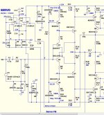
If you have spare few minutes and can swith off your soldering iron please.
I will need some advice.
I have build similar IPS as 1.3H cfp, but with diamond input. Sound is absolutley fine for me but I do not know what is the best way to implement trimpot offset adjustment (without affecting pssr).
On the schematic bellow there is POT1 (+-1.2V adjustment bitt too little) and POT3 for offset. I have to get rid off POT1 becouse it has too low adjustment range, would the POT3 be OK ?
If you can suggest me some better option please for manual offset adjustment ?
THX
Attachments
ostripper
If you have spare few minutes and can swith off your soldering iron please.
I will need some advice.
I have build similar IPS as 1.3H cfp, but with diamond input. Sound is absolutley fine for me but I do not know what is the best way to implement trimpot offset adjustment (without affecting pssr).
On the schematic bellow there is POT1 (+-1.2V adjustment bitt too little) and POT3 for offset. I have to get rid off POT1 becouse it has too low adjustment range, would the POT3 be OK ?
If you can suggest me some better option please for manual offset adjustment ?
THX
"Pot3" impedance seems too high to force offset null at the current FB
node.
On the "NAD V1.2" , I used a negative FB servo to adjust the high Z
diamond input. This worked well (thimios) , requiring only picoamps to
adjust the diamond.
The other way to trim offset is to bias the low Z current feedback node.
This requires much more current (mA's) , I used a TL072 output which
used 2+ma to "steer" the offset to zero.
For a trimmer , Bonsai's NX uses a low Z pot + decoupling fed to another
resistor which matches the higher value current FB resistor. The (nadV1.3-below)
uses 1.5k for CFB and "servo return".
It is better to bias offset from a regulated auxiliary supply , as this does
not affect PSRR much.
Hope that helped !! 🙂
OS
Attachments
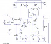
I have the Symasym IPS populated and want to test it before I hook it up to the OPS. Will the circuit I have attached work for testing? Can I measure across the "Load resistors" to attain the VAS current?
Thanks, Terry
Thanks, Terry
Attachments
Last edited:
Yes but 1k may be a little high to realistically simulate the OPS. I'd suggest using 470R so the target current drops a voltage similar to the VBE circuit in the OPS.
- Home
- Amplifiers
- Solid State
- Slewmaster - CFA vs. VFA "Rumble"