What is the explanation for the tilt of the tops of the square waves at the low frequencies? I understand the rounding of the leading edges of the high frequency scope readings but not what I am seeing on the low end.
Too much lead compensation ... PS , I know this by simulation (and building
3 sym varients).
The link also backs this up.
"symasui" has NO lead comp. , and it RULES in LF performance.
"real world solution" .... reduce the 22pF cap in parallel with the feedback resistor to 10pF (or even eliminate it).
edit - symasui does have a 2.7pf lead cap .... still not 22pf !!
OS
Last edited:
Too much lead compensation ... PS , I know this by simulation (and building
3 sym varients).
The link also backs this up.
"symasui" has NO lead comp. , and it RULES in LF performance.
"real world solution" .... reduce the 22pF cap in parallel with the feedback resistor to 10pF (or even eliminate it).
OS
What comprises the "lead compensation" and can it be fixed in this circuit?
Oops,we were typing at the same time.
Last edited:
OS, you're talking about higher frequency curves, not the lower frequency ones. 22pf lead comp cap does not affect LF performance.
Right 🙂
Right 🙂
Terry,
If it is supposed to be a true rms dmm it will for sure say that on the front of the meter. I have a couple of them and they do cost more than a similar meter that is not supposed to be true rms.
OTOH if the signal is a sinewave, all multimeters are RMS - that's just how they are set up.
They start to deviate in two cases: a) when the frequency gets too high for an accurate rectification, or b) if the signal starts to deviate from sine wave shape.
So as long as you measure sines not higher than a few kHz, your multimeter should correctly indicate RMS.
Jan
OS, you're talking about higher frequency curves, not the lower frequency ones. 22pf lead comp cap does not affect LF performance.
Right 🙂
I think lead compensation to give higher open loop gain at high frequency. I use it with small miller cap to get higher slew rate.
I think lead compensation to give higher open loop gain at high frequency. I use it with small miller cap to get higher slew rate.
Right, but it does not affect LF range - the one, initial question was about )
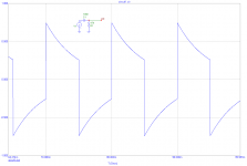
What is the explanation for the tilt of the tops of the square waves at the low frequencies? I understand the rounding of the leading edges of the high frequency scope readings but not what I am seeing on the low end.
LF roll off. Pls check the images attached. Capacitor charged by resistor, voltage drop across capacitor. Time constant RC.
Attachments

LF roll off. Pls check the images attached. Capacitor charged by resistor, voltage drop across capacitor. Time constant RC.
Exactly
The bigger capacitor is -> the higher time constant is -> the lower low-cut frequency is -> the smaller tilt at a given frequency is
Last edited:
Low frequency roll-off at some 5Hz (-3dB) is no problem. All I wanted to show is that any LF roll-off makes exponential decay at step response with RC time constant. The lower square wave frequency, the more you will see it. Guys, this belongs to absolute basics of analog circuits and understanding is necessary for ANY diyer.
Hi Pavel,
I'm not questioning the validity of your data, I'm asking because I want to learn. I have only recently begun testing with square waves and want to be able to understand what they mean to the operation of the amp. How to know when there is something wrong or when I am seeing normal behaviour. I don't want to be trying to fix something that ain't broken.
Blessings, Terry
Thank you Pavel. For me anyway everything is new so I am still learning all the basics. The resistor in the capacitor resistor equation sets the time constant, the larger the resistor the slower the time constant? Or increase the capacitance with the same resistor and the same effect?
Yes, time constant (and thus low-cut frequency) depends on both coupling capacitor value and input impedance. For a given low-cut frequency, the higher input impedance is - the lower cap value is required. F = 1 / (2 * π * R * C)
Last edited:
Thank you Pavel. For me anyway everything is new so I am still learning all the basics. The resistor in the capacitor resistor equation sets the time constant, the larger the resistor the slower the time constant? Or increase the capacitance with the same resistor and the same effect?
Yes the RC time constant is the product of the R and C, R*C=TC. You can calculate the cut-off frequency if you like:
Fc=1/(2*pi*R*C), where R is in Ohms and C is in Farads and the result, Fc, is in Hz.
For example, using some values I generally like to use: Input C is 10µF and input R is 10kΩ.
Fc=1/(2*pi*R*C)=1/(2*3.14*10000Ω*0.00001F)=1/0.628=1.6Hz
Raising either or both increases the time constant. There is no issue with the sloped tops when viewing low frequency squares, that is just the 'high pass' filter response you are seeing created by the input coupling capacitor and the input impedance of the amplifier itself.
So long as the -3dB point is sufficiently low there will be no issue with bass response even though you may see a slope on the square wave testing. The low frequency cut-off is fine in the neighbourhood of 2Hz-5Hz. I like to keep my high and low frequency cut-off points to be about a factor of 10 outside the audio band, so my 1.6Hz input section values as above satisfiy that requirement.
If you want to measure your bandwidth, I usually do this: I set my generator for a sine wave at 1kHz to get 10V peak at the amplifier output, note the input level. I reduce the frequency until I have 7.07V peak output (this is the -3dB point assuming the usual 'single pole' filter, one R and one C) and verify the input level hasn't changed. If required, adjust both input level and frequency until I have the same level input as it was at 1kHz and 7.07V peak output. The frequency at this point is the low frequency cut-off. You can do the high end the same way and measure the high frequency cut-off too.
OK, so is low frequency roll-off a bad thing? This amp seems to have plenty of bass.
Terry, there's nothing bad about it. An exercise I proposed in post #2436 is aimed to see if there is some drop in frequency response at the frequencies up to 10Hz, so that we see what the low-cut frequency actually is.
Cheers,
Valery
Yes, every diyer should make his own simple multiplication and division 😉
Ohm's law and Fc calculations are so simple that anyone should do it and prevent possible mistakes and delays.
Ohm's law and Fc calculations are so simple that anyone should do it and prevent possible mistakes and delays.
Thank you all for the lessons here. Yes I can do that math, it is rather simple once you know what values to place where. I will copy these posts and place them in a folder so I don't have to go looking for them.
Many thanks,
Steven
Many thanks,
Steven
- Home
- Amplifiers
- Solid State
- Slewmaster - CFA vs. VFA "Rumble"