I have the Symasym IPS populated and want to test it before I hook it up to the OPS. Will the circuit I have attached work for testing? Can I measure across the "Load resistors" to attain the VAS current?
Thanks, Terry
Start on the high side (less current - 470R?) for the current source.
This will underbias the VAS , making it "short" on total current.
This , in turn ... will underbias the OPS (safe !!). Slowly lower the CCS
resistor value, (a 500R trimmer) ...to get into an optimum range for the OPS (4.5-5.5ma).
The "sym's" CCS is the main player in determining the VAS current (same
as my "symasui").
OS
Thanks OS
You are a star !!
I think I will try to adjust the offset at the input becouse it requires very low power for the job.
I am just wondering why allways servos are injected in NFB loop and very rarley at the input ?
You are a star !!
I think I will try to adjust the offset at the input becouse it requires very low power for the job.
I am just wondering why allways servos are injected in NFB loop and very rarley at the input ?
Last edited:
Hi OS,Start on the high side (less current - 470R?) for the current source.
This will underbias the VAS , making it "short" on total current.
This , in turn ... will underbias the OPS (safe !!). Slowly lower the CCS
resistor value, (a 500R trimmer) ...to get into an optimum range for the OPS (4.5-5.5ma).
The "sym's" CCS is the main player in determining the VAS current (same
as my "symasui").
OS
Could you please clarify a little for me? Which resistor is the CCS? Are you saying to replace it with a 500R pot? Will a pot take the current OK?
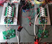
OK, I tested the boards and as Jason said, the current doesn't change a lot as the voltage goes up. I installed the 470R load resistors. I read 1.8V across the load resistors so if I'm right I have 3.6mA output. I know that is lower than the 4.5-5mA but I thought I would try it anyway. Seems to work just fine so I want to ask how the lower current affects things so I can learn something here. The little VAS transistor do get a little hot but certainly not boiling. I suppose that may be because the lower bias. I put some heatsinks on them anyway. The IPS is running on +-74V. OPS rails are at +-77V. The offset is < 5mV. That is the lowest I have seen to date on an amp that doesn't have an offset pot. Pretty impressive. Oh, did I mention this amp sounds lovely. I have changed my mind about offering my extra OPS boards. A few of these are going to become complete amps. Just too nice!
Blessings, Terry
Blessings, Terry
Attachments
Hi OS,
Could you please clarify a little for me? Which resistor is the CCS? Are you saying to replace it with a 500R pot? Will a pot take the current OK?
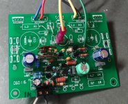
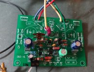
R11 on your schema is the resistor , Q7/8 are the CCS. These devices
regulate current to the input differential.
With the pot , you could adjust VAS current from 2-7ma . No need to switch
other resistors - preserve the symasym sound 😀 .
OS
OK, I tested the boards and as Jason said, the current doesn't change a lot as the voltage goes up. I installed the 470R load resistors. I read 1.8V across the load resistors so if I'm right I have 3.6mA output. I know that is lower than the 4.5-5mA but I thought I would try it anyway. Seems to work just fine so I want to ask how the lower current affects things so I can learn something here. The little VAS transistor do get a little hot but certainly not boiling. I suppose that may be because the lower bias. I put some heatsinks on them anyway. The IPS is running on +-74V. OPS rails are at +-77V. The offset is < 5mV. That is the lowest I have seen to date on an amp that doesn't have an offset pot. Pretty impressive. Oh, did I mention this amp sounds lovely. I have changed my mind about offering my extra OPS boards. A few of these are going to become complete amps. Just too nice!
Blessings, Terry
They are nice , aren't they ?
All 5 of my IPS's are "nice" , too. Thimios,bimo and NAF never had any real
issue.
I might not be around for a while ... (moving back to Tennessee).
But ... all 5 of the main IPS projects are debugged and will really
"fly" with your OPS !
Have fun !
PS - In july ... I will do another 5 REAL good (different) IPS.
- An IC one , and a few more Japanese classics (updated ., of course).
OS
No doubt, nice! Looking forward to your "new" designs. I'm having fun trying out "other" designs too. This Symasym front end sounds really, really nice. I have been A/Bing it all day with other amps. Folks should probably not make themselves and A/B setup. They will be disappointed by how little difference can be heard between different topologies. Once you get to super low THD there really isn't to much difference in the sound. I probably need to learn to measure for all that stuff so I can "see" a difference because I sure can't hear it. 😀
I'm going to buy an HP laserjet so I can do home etched boards. I just can't get myself to pay $8 each for photo etch boards when I can have factory made boards for half that. I do want to start etching again so I don't have to rely on folks to produce gerbers.
I want to try each of your designs. Etching looks like the only way to do all of them.
Good luck with your move.
Blessings, Terry
OS,
Be safe on your move. I will look for your return to the thread once you have your things sorted out. Thank you for all that you have done already.
Steven
Be safe on your move. I will look for your return to the thread once you have your things sorted out. Thank you for all that you have done already.
Steven
PS - In july ... I will do another 5 REAL good (different) IPS. An IC one ... OS
OStripper,
I'm gonna hold to to it! I look forward to seeing what you come up with for an IC driven version. The aging UREI 6250 is my reference for such amplifiers. I should have a few of your output sections built and on my bench by then.
Have a good move. Tennessee is a beautiful place.
I sat down and and hooked up the scope and generator. I played some square waves set to 10Vac into an 8 ohm dummy load. I am attaching the pics.
Blessings, Terry
Blessings, Terry
Attachments
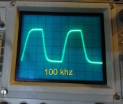
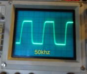
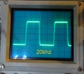
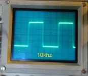
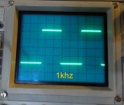
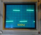
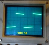
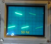
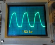
What is the explanation for the tilt of the tops of the square waves at the low frequencies? I understand the rounding of the leading edges of the high frequency scope readings but not what I am seeing on the low end.
I sat down and and hooked up the scope and generator. I played some square waves set to 10Vac into an 8 ohm dummy load. I am attaching the pics.
Blessings, Terry
Terry, they actually look very good, confirming rock solid stability and good bandwidth of the circuit at the higher end.
Tilted tops at lower frequencies may be an indication of certain bandwidth limitation at the lower end (caused by not enough value of coupling capacitor at the amp's input, for example).
Can you do a simple experiment - see the p-to-p amplitude of the sine waves on the scope screen for, let say, 1KHz, 50Hz, 20Hz and 10Hz, with the same amplitude range setting at the scope?
Drop the pictures here and we'll see if this is the case...
Those readings were done with the same amplitude. I set the generator so that I read 10vac output at the speaker jack with a 1k signal. Then I simply changed frequencies and switched the dial on the scope to keep approximately three waves visible on the screen. I didn't touch the amplitude again during the test. If you look at the screen shots you will see that they are at the same amplitude.
As for the input cap, I just used a small 10uf, 100v, polarized, electrolytic. I'm sure the measurements could be improved with a better cap though I'm not sure if you could hear it. On the CFA IPS, the HF waves looked similar to these until I bypassed the input cap.then they became very square. The sound was the same so I'm still not convinced that 100khz square wave shapes have much bearing on how an amp sounds.
Blessings, Terry
Right, we just need to see the sine amplitudes at the low frequencies - then we can clearly see if the cap value is enough
Sorry I didn't notice you said sine wave. I will post those up in the morning. The amp has very strong bass response. It is actually pretty impressive.
Blessings, Terry
Blessings, Terry
- Home
- Amplifiers
- Solid State
- Slewmaster - CFA vs. VFA "Rumble"