I'm going to buy an HP laserjet so I can do home etched boards. I just can't get myself to pay $8 each for photo etch boards when I can have factory made boards for half that. I do want to start etching again so I don't have to rely on folks to produce gerbers.
Blessings, Terry
Terry I just purchased a HP LaserJet Model P1102W, I set the density to 5 and got almost perfect results. HP tech support got me going, as I had issues with the driver and the XP operating system on the computer I was installing it on. I got it on sale at Office Depot for $100 plus tax. I find it great and the only thing I detract from it is its small capacity toner cartridge. I will try a refill when the current "Starter" cartridge runs out. I am quite happy with the overall results. 😀
Are photo etch and laser transfer processing the only way to do this by diy or are there other means? Do you have to use a photo etch board or is there another way or other type of board that you can still use a transfer method. Does this mean that you can't do double sided boards or are those also available in a photo etch board? If you did that I imagine that the alignment of two sides would be the sticking point but could be overcome with an alignment setup I can imagine in my mind. Helps to come from a tooling background.
I have used in the past photo sensitive aluminum sheet to print patterns on for making tooling. We used Hydrogen peroxide as the developer back in the day but the sheet was very expensive and we used UV bulbs if I remember correctly to expose the sheet.
I have used in the past photo sensitive aluminum sheet to print patterns on for making tooling. We used Hydrogen peroxide as the developer back in the day but the sheet was very expensive and we used UV bulbs if I remember correctly to expose the sheet.
There are two popular types. Photo etch requires photosensitive boards that have to be exposed to UV light and then developed much like film. The other is iron transfer using a laser jet printer and then the image is ironed onto a bare copper clad PCB. from there the etching process is the same. Both can produce double sided boards but most folks just use jumpers where needed and stick to single sided boards. At the price point, professionally produced boards are cheaper if you can get the gerbers. The place I use limits quantities to lots of 5 boards so you usually try to get friends to share with you and get at least 5 pair. I'm going to go with the laser transfer because the boards are less than half the cost of photosensitive boards and I have all the equipment except for a laser printer which I will purchase this month.
Blessings, Terry
Blessings, Terry
Thanks Terry. It seems there are so many shops out there offering quick turnarounds and low prices on low quantities that I have questioned the sanity of doing it myself and needing the chemistry to do it. I did photography years ago and remember the baths and being in a darkroom. I have seen others talking about only doing this outdoors due to the toxic nature of the fumes given off in the process. And what do you do with the bath chemicals once they are contaminated with the copper byproducts? I guess if you are out in the wilderness or somewhere that this service is not available it would be the way to go. I would have to purchase everything including a laser printer, not a bad idea when I look at the cost of ink for my inkjet printer!
OK, here are some screen shots of sine waves. I set the generator so that I had a little over 10Vac at 1khz and left the level there for all frequencies.
Blessings, Terry
Blessings, Terry
Attachments
-
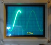 20hz sine.jpg959.3 KB · Views: 467
 -
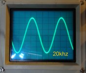 20khz sine.jpg804.6 KB · Views: 121
 -
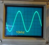 10khz sine.jpg877.5 KB · Views: 120
 -
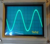 1khz sine.jpg836.2 KB · Views: 362
 -
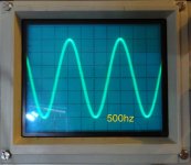 500hz sine.jpg834.3 KB · Views: 412
 -
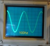 100hz sine.jpg710.8 KB · Views: 413
 -
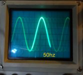 50hz sine.jpg793.1 KB · Views: 434
 -
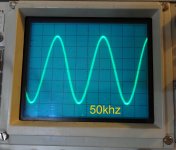 50khz sine.jpg870.4 KB · Views: 110
 -
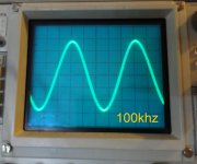 100khz sine.jpg829.7 KB · Views: 127
 -
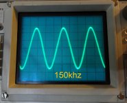 150khz sine.jpg822.5 KB · Views: 137
Yes Terry but people wanted to see you do 10Hz 5Hz etc to see what the low end roll off is like 🙂
This is what I was responding to. I'll see if my equipment will do what you are asking for.
EDIT; Can't do. My Sine wave generator only goes to 20hz, no lower.
Terry, they actually look very good, confirming rock solid stability and good bandwidth of the circuit at the higher end.
Tilted tops at lower frequencies may be an indication of certain bandwidth limitation at the lower end (caused by not enough value of coupling capacitor at the amp's input, for example).
Can you do a simple experiment - see the p-to-p amplitude of the sine waves on the scope screen for, let say, 1KHz, 50Hz, 20Hz and 10Hz, with the same amplitude range setting at the scope?
Drop the pictures here and we'll see if this is the case...
EDIT; Can't do. My Sine wave generator only goes to 20hz, no lower.
Last edited:
Yes Terry but people wanted to see you do 10Hz 5Hz etc to see what the low end roll off is like 🙂
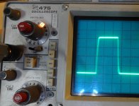
I can read it from 50Hz square that Terry had posted. F(-3dB) is about 5Hz.
Attachments
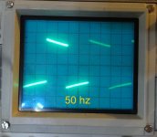
Well like others have said, the low end roll off isn't any issue and is entirely normal. Adding in a highpass always creates a sloping top and bottom on a square wave. Usually one chooses a corner frequency some 10x lower than the lowest frequency you expect the amplifier or equipment to produce. So in this case 2Hz. The usual 47u + 10k input impedance lands you pretty close to this.
This is what I was responding to. I'll see if my equipment will do what you are asking for.
EDIT; Can't do. My Sine wave generator only goes to 20hz, no lower.
Terry, at least up to 20Hz at the lower end it looks perfectly fine - no sign of amplitude drop, so never mind. It is a very good performance in all aspects. Simple calculation - Fc=1/(2*pi*R*C) - with 10uF cap and roughly 20kOhm input impedance shows the low-cut frequency at around 0.8Hz, so no problem at all.
Enjoy a great amp!
So in this case 2Hz. The usual 47u + 10k input impedance lands you pretty close to this.
47uF + 10k makes 0.338 Hz/-3dB
Simple calculation - Fc=1/(2*pi*R*C) - with 10uF cap and roughly 20kOhm input impedance shows the low-cut frequency at around 0.8Hz, so no problem at all.
You know, it is a feeback resistor (R30) from -In followed by a series capacitor to ground (C19) that estimates F(-3dB) low frequency corner...., if we speak about symasym. It has DC gain = 1.
http://web.telecom.cz/macura/sym5_2.png
symasym
Last edited:
It is really a nice combination. Sounds lovely I can't wait to try some of OS's IPS. I have CFA-XH boards coming from China. Production is complete so should see them in a couple of weeks. As soon as Jason makes some more Gerbers for the other IPS I'll order some of those as well.
I didn't hear from OS about the importance of having a 4.5-5mA output from the IPS. This seems fine.
Blessings, Terry
I didn't hear from OS about the importance of having a 4.5-5mA output from the IPS. This seems fine.
Blessings, Terry
You know, it is a feeback resistor from -In followed by a series capacitor to ground that estimates F(-3dB) low frequency corner...., if we speak about symasym. It has DC gain = 1.
Ah, OK - I see what you mean. Right, it cuts higher, than the input RC...
I use servo in most of the cases, so feedback cap does not come to my mind right away 🙂
Last edited:
0.338Hz.
Indeed it does. For some reason my calculation was out by a factor of 10 the first time around. The only explanation to that is I must have typed in 4.7u instead of 47! That'll teach me to double check everything first.
Indeed it does. For some reason my calculation was out by a factor of 10 the first time around. The only explanation to that is I must have typed in 4.7u instead of 47! That'll teach me to double check everything first.
Terry -
just one question. Do you use AC or DC input mode coupling with your oscilloscope, for a measuring channel?
Especially for square wave measurements.
just one question. Do you use AC or DC input mode coupling with your oscilloscope, for a measuring channel?
Especially for square wave measurements.
@ still4given
Very nice sines up to 150kHz 🙂
It'd be interesting if you could compare 20 - 20kHz THD with 10uf V 100uf input cap 😉
Very nice sines up to 150kHz 🙂
It'd be interesting if you could compare 20 - 20kHz THD with 10uf V 100uf input cap 😉
Terry,
I see that your Oscope is available in both 100mhz and 200mhz versions, do you know which yours is? I was looking at the price for a used unit and see the two models, the price looks reasonable for something like that.
I see that your Oscope is available in both 100mhz and 200mhz versions, do you know which yours is? I was looking at the price for a used unit and see the two models, the price looks reasonable for something like that.
- Home
- Amplifiers
- Solid State
- Slewmaster - CFA vs. VFA "Rumble"