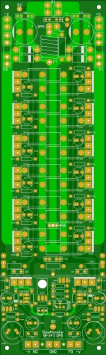
Nice work!Here's my preliminary, double sided, two output pair, semi SMD, wolverine PCB.
I'll hopefully have it doing something by the end of the week.
Wolverine semi SMD......Interesting😱
all tested 10VRMS/4R
Gnome........1.72MHz
Nad ........1.2MHz
Spooky.......850MHz - (KHz) 😱
Symasui......830MHz -(KHz) 😱
CFA-X V1.3...530KHz
CFA-X V1.2...520KHz
All these mesurments low pass filter on board.
Thimios.
Timios,
My I Kindly ask You which IPS & OPS Transistors You used for the 850 MHz measurements -Typo ?
Thnx
Andreas
Did you mean spooky?Timios,
My I Kindly ask You which IPS & OPS Transistors You used for the 850 MHz measurements -Typo ?
Thnx
Andreas
Output it's the same for all these input.
mje 340.350 for capac.mult. predriver,Vbe mult.
2sa1837.c4793 drivers
2sc3264 ,a1295 out
At all my inp. i used tsca970 ,a1015, c1815 ,c1845, c3503, a1381.
If you want to know the exactly configuration i can check for this again
Thimios.
Last edited:
Timios,
My I Kindly ask You which IPS & OPS Transistors You used for the 850 MHz measurements -Typo ?
Thnx
Andreas
That was definitely typo... KHz...
Thimios, this is not a UHF radio-transmitter 😛
Nice work!
Wolverine semi SMD......Interesting😱
Thanks 🙂
I routinely use SMD stuff and I needed this design specifically to be able to fit into a smallish space. The end goal is to have 2x slewmaster + some input stage on one 75x300mm heat sink, which has about 65x300mm mounting space. These ones specifically are going on a 100x200mm heatsink.
The smallest SMD stuff I've managed to work with was a 100 pin TQFN MCU with 0.4mm pitch and that was a touch smaller than I am happy with. It was by accident too as I thought I had ordered the 0.5 pitch part, much to my surprise when it arrived. It was half the price of the 0.5 pitch part. Now I could see why, no one ordered them lol, too small.
That was definitely typo... KHz...
Thimios, this is not a UHF radio-transmitter 😛
It might be called Spooky, but we're not really trying to communicate with aliens.

Timios,
The Meas. Setup would be nice know more about it.
Those meas. which denoted with MHz are in Mega Hertz territory and none of those transistors even with ultra controlled SMD design with 6 layer Teflon PCB board aren't possible to achieve those frequencies (850 MHz).
You perhaps mean 850 KHz - This is much easily achievable.
Thnx
Andreas
I know the topic of discussion has moved on from the OPS but I was playing about with my OPS artwork since I'm thinking about a new order to go with the IPS and this occurred 😱. It should still (just) fit a chunk of Heatsink USA 10.080" extrusion  and OS's choice of drivers will support the added pair... Maybe I'm just getting goofy...
and OS's choice of drivers will support the added pair... Maybe I'm just getting goofy...Attachments
Hi Guys,
Speaking of OPS, I have a few boards from the Gerbers Jason made that match the boards in Post #1201. I don't want to interfere with the Group Buy. If interested just PM me. I'll probably have some CFA-XH boards too since I have to order a small quantity.
Blessings, Terry
Speaking of OPS, I have a few boards from the Gerbers Jason made that match the boards in Post #1201. I don't want to interfere with the Group Buy. If interested just PM me. I'll probably have some CFA-XH boards too since I have to order a small quantity.
Blessings, Terry
I know the topic of discussion has moved on from the OPS but I was playing about with my OPS artwork since I'm thinking about a new order to go with the IPS and this occurred 😱. It should still (just) fit a chunk of Heatsink USA 10.080" extrusion
Jaosn, any chance you can post pdf files for those of us who want to do toner transfer? thanks....
Jaosn, any chance you can post pdf files for those of us who want to do toner transfer? thanks....
The latest version is intended for board house manufacture, since it is a double sided layout. The actual output section could do solely with normal single sided construction but there are a few traces that are on the component side in the lower current areas of the board. That said I can output DIY friendly files in PDF and folks can either use wire jumpers or if they are good at home etching could do a fully double sided board.
OK, just 'cause AJT asked for it... Here is a ZIP of the following:
Drill Chart
Bottom Copper
Top Copper (Mirrored)
Top Silk (Mirrored)
Please note the added outputs and supporting components do not have any component designators because there is no schematic showing six pairs. The circuit is the same as the five pair version with an added pair.
Drill Chart
Bottom Copper
Top Copper (Mirrored)
Top Silk (Mirrored)
Please note the added outputs and supporting components do not have any component designators because there is no schematic showing six pairs. The circuit is the same as the five pair version with an added pair.
Attachments
all tested 10VRMS/4R
Gnome........1.72MHz😱
Nad ........1.2MHz
Spooky.......850MHz
Symasui......830MHz
CFA-X V1.3...530KHz
CFA-X V1.2...520KHz
All these mesurments low pass filter on board.
Thimios.
Spooky.......850KHz
Symasui......830KHz

Jason,
What are you doing, adding another 50 watts per board at 8 ohms? Will anything else need to change with this addition or does everything previous to the outputw stay the same no matter the number of output devices?
What are you doing, adding another 50 watts per board at 8 ohms? Will anything else need to change with this addition or does everything previous to the outputw stay the same no matter the number of output devices?
Jason,
What are you doing, adding another 50 watts per board at 8 ohms? Will anything else need to change with this addition or does everything previous to the outputw stay the same no matter the number of output devices?
I'm not trying to actually change anything, it is just a conceptual piece. IF one were to pursue such a beast nothing changes except adding the sixth pair and supporting components. I recall a user (or maybe more than one) suggesting six pair to evenly distribute the outputs over two heat sink sections so I thought I'd see what it looks like. It is actually very easy to alter the art for any number of pairs from a single pair up to total goofiness.
I wonder how many pairs one can go to and still keep the amplifier fast and stable? Presumably there is a limit.
I think at about seven pairs the drivers are at risk driving from high rails into lower impedance, so there is the practical limit IMHO.
I wonder how many pairs one can go to and still keep the amplifier fast and stable? Presumably there is a limit.
That is a really good question!
I think one main problem with heavy paralleling in parasitics. The inductances and trace coupling adds up and you get crazy oscillations. A ground plane would probably fix this.
Beyond that, unless you bulk up the drivers and VAS and input stage, then it won't be able to drive all those outputs, at least not at the same speed and grace. Cascading more stages may help to drive, but that will introduce a lot of poles that will reduce stability, meaning it will again be slow after being stabilized. By paralleling stages however you can increase drive without losing speed. So if you use many paralleled outputs, it may be appropriate to use parallel transistors in preceding stages.
Paralleling output transistors may be preferable to using super-high-power transistors, because the Ft of lower-power transistors will be better, which means a smaller rectifier-like "recovery" spike during switching.
still4given:
Use the lowest output voltage available on your square wave source that is still clearly visible on the scope. Square waves stress an amplifier much more than audio, so they need to be tested at a low level to be applicable to playback behavior.
Last edited:
I was more thinking in terms of adding more to increase the amps capabilities into lower ohm loads so one wouldn't need to increase the rail voltages. Of course that still places greater demands on the previous stages too.
Use the lowest output voltage available on your square wave source that is still clearly visible on the scope. Square waves stress an amplifier much more than audio, so they need to be tested at a low level to be applicable to playback behavior.
No more toasted outputs
No more toasted outputs
Last edited:
- Home
- Amplifiers
- Solid State
- Slewmaster - CFA vs. VFA "Rumble"