It would be interesting to see report if someone try this. I tried some tricks to rise low h but the sound image was blurred.
Tried it ? (below) is a amp that has won many audiophile reviewer
awards (10/10 - "breathtaking").
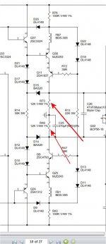
12K loads with real large cascode devices for the hawksford.
I simulated with no or high value resistors = 6-10ppm.
As it is below - .01% !! High H2 - but it win awards - ???
They purposely "crippled" the VAS in return for H2 - my simulation
does not lie.
PS - this can be tried on all my hawksford based IPS's - the pads are there.
OS
Attachments
Tried it ? (below) is a amp that has won many audiophile reviewer
awards (10/10 - "breathtaking").
12K loads with real large cascode devices for the hawksford.
I simulated with no or high value resistors = 6-10ppm.
As it is below - .01% !! High H2 - but it win awards - ???
They purposely "crippled" the VAS in return for H2 - my simulation
does not lie.
PS - this can be tried on all my hawksford based IPS's - the pads are there.
OS
I've not tried the same circuit as above, but it sounded better without harmonics on my design. I am wonder if it is h2 that make it outstanding or other benefits like lower open loop gain, lower global feedback, increased stability... This is great opportunity to find out some audio truth.
OS,
I would think that those who are in love with SE tube stages would be the ones to want that type of obvious harmonic added distortion. I agree that perhaps the harmonic distribution of all the added even and odd harmonics could and would have an audible signature I am not sure that this has ever been quantified as to what would be ideal. My belief is add nothing and remove nothing from the original sound and you are where you want to be.
Thimios,
You are the man again. Can't wait to read what you think of the sound when you have that done. Comparison to the original CFA-X would be interesting.


Hi maouna ,i haven't the wolverine🙁wow!!! thimios you have every single ips!!! 😀
Thimios,
As long as you don't start changing the input section with every new song you play I'd say your going to be okay! Keep up the great work.
Steven
As long as you don't start changing the input section with every new song you play I'd say your going to be okay! Keep up the great work.
Steven
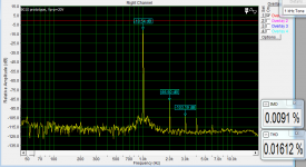
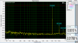
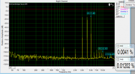
I think there is worth of experimenting with input stage too, ccs vs resistor feed to input pair (bellow is resistor example). The amp from measures bellow was sounding extremly smooth without any harshness.
The ''audio truth'' will be prapobly hard to find but who is not trying will not find it anyway.
I found myself that amps with spectrum like bellow I like the most (not all of them).
I am doing something wrong with spice simulations cause the real life amps have totally different harmonics spectrum. I am always taking 10 samples for FFT but the picture of spectrum is different anyway.
Attachments
i wonder which one sounds best... thimios ,have you made any sound tests among these input stages?
i have the cfa-x boards etched but no components yet so my progress will be slow 🙁
i have the cfa-x boards etched but no components yet so my progress will be slow 🙁
Hi Guys,
OK I finally go all my parts and started testing things. Both of my IPS measure fine and the first OPS seems fine. With 18K jumping the inputs I was able to set the bias at 400mA, 12mV across each emitter resistor. The second OPS seems to have problems. It seemed to measure ok but C125 is getting hot. I thought maybe I had a bad cap so I replaced it but the new one is getting hot too. Any suggestions?
Thanks, Terry
Last edited:
The only way that cap is going to heat up is if it is heating due to ripple. Have you looked to see if there is any evidence of Oscillation? Maybe install the optional CSA and CSB 68pF just to see.
Hi Jason,
I should have replied sooner. I think the problem was just that the cap needed to form. I put in a 30W light bulb in my bulb circuit and let the amp sit for about a half hour at 30V rails and then bumped it up to 70V for another half hour and now the caps are cool. I just got through testing both channels. With an 8ohm load and a 1K sine they clip at about 48Vac on +-78V rails. Square waves look perfect. I just A/B'd it against my DX MKIII. I think it bested it. This is maybe the best sounding amp out of the box so far. I can't wait to try the full blown CFA-XH. Hard to imagine it sounding better. This thing rocks!!!
I need some bigger heatsinks. I just mounted them to a pair I had sitting around. Not enough for these rails.
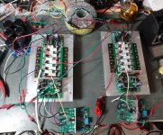
I am attaching a pic of the spider webs. Enjoy!
I should have replied sooner. I think the problem was just that the cap needed to form. I put in a 30W light bulb in my bulb circuit and let the amp sit for about a half hour at 30V rails and then bumped it up to 70V for another half hour and now the caps are cool. I just got through testing both channels. With an 8ohm load and a 1K sine they clip at about 48Vac on +-78V rails. Square waves look perfect. I just A/B'd it against my DX MKIII. I think it bested it. This is maybe the best sounding amp out of the box so far. I can't wait to try the full blown CFA-XH. Hard to imagine it sounding better. This thing rocks!!!
I need some bigger heatsinks. I just mounted them to a pair I had sitting around. Not enough for these rails.
I am attaching a pic of the spider webs. Enjoy!
Attachments
Last edited:
Very cool Terry! Glad to see another FrankenMonster running. I'm going to get some time in on the CFA-XH art this weekend.
jaagut
I can give you small advice, seem you are using non metalized film resistors (they just to be 0,2W) I have came across a failure of those resistors (burned one nice speaker), better of use metal film resistors 0,6W - they are more bullet-proof.
...
Hi Bimo - Thanks, I'll try your tip. 🙂
I have been looking back through the thread and I can't seem to find what the suggested bias should be. I have this set at 400mA per rail. It just seems way too high. I've never had an amp get this hot this quickly.
I set mine for 50mA per device, 250mA per rail and it seems very thermally stable.
What did you use for pre-drivers? I checked mine and I have the MJEs in that position and the KSA/KSC for cap multiplier and VBE.
What did you use for pre-drivers? I checked mine and I have the MJEs in that position and the KSA/KSC for cap multiplier and VBE.
Last edited:
The "H" only differs from the "VSSA" (CFA-X - first version) by the
addition of the hawksford and the compensation options.
The only expected advantages are -
1. More linear at high output .... THD stays low at 120V p-p.
2. Simulated side by side , the "H" has 1/2 the THD ... any frequency.
3. It slews faster by 2X and seems to tolerate very low compensation
values (and lower current FB to get that slew).
Audibly - these attribute's might "sound better" . In fact ...at high output ,
most likely.
This is best left to "golden ears" 😀 ...
PS - play around with the comp. and VAS load R's ,and "magic" might occur 🙂 .
OS
I set mine for 50mA per device, 250mA per rail and it seems very thermally stable.
What did you use for pre-drivers? I checked mine and I have the MJEs in that position and the KSA/KSC for cap multiplier and VBE.
OK, maybe I'm doing something wrong. I hooked an ammeter to the - rail and a volt meter across one of the emitter resistors. when the voltmeter reads 12mV I see 400mA on the ammeter. 12mV across a .22R should be 54mA per device. Why do I see 400mA with 10 devices?
Thanks, Terry
OK, maybe I'm doing something wrong. I hooked an ammeter to the - rail and a volt meter across one of the emitter resistors. when the voltmeter reads 12mV I see 400mA on the ammeter. 12mV across a .22R should be 54mA per device. Why do I see 400mA with 10 devices?
Thanks, Terry
You also have the driver/ predriver and (multiplier) + IPS using current.
I read >50ma per rail to power the above.
Depending on the IPS draw from the multiplier's , this could
be higher depending on the IPS used.
PS - read the voltage drop across the 2 -1W 4.7R's near the drivers.
OS
Last edited:
Yes, didn't have my thinking cap on. We have to account for the driver, pre-driver, capacitance multiplier and IPS currents, so 400mA isn't out of line.
- Home
- Amplifiers
- Solid State
- Slewmaster - CFA vs. VFA "Rumble"