7 or 8 amp fuses on the slewmaster rails should avoid "burning amps".AJT, you must read from the beginning. Keantoken opinion is good for helping me to understand many things here.
The bias current can be set from class B to class A.The trade-off is depend on the designer choice. I want to know how to calculate or to sim optimum bias to get lowest crossover distortion. Self called it optimum bias of class B, Keantoken said "sweet spot" 😀. It is importance when builder do not have distortion meter.
OStripper, is current limiting for protection on output transistor useful or not? Is it affecting the sound?
HK680 has 6.3A fast blow...
Many OEM's just use a marginal PS as current protection .. small trafo
and smaller PS caps will "droop" for 4R loads. This is how they avoid
warranty issues 😀 .
DC protect with a solid state output relay (Bonsai)... Solid State Loudspeaker Relays for Audio Amplifiers
Best for reliability and NOT affecting quality.
OS
Ostripper,
Wouldn't an undersized power supply just clip earlier than one that is properly sized? Or is this only related to slew rate and clipping the outputs causing problems with the protection of the amplifier?
Wouldn't an undersized power supply just clip earlier than one that is properly sized? Or is this only related to slew rate and clipping the outputs causing problems with the protection of the amplifier?
Ostripper,
Wouldn't an undersized power supply just clip earlier than one that is properly sized? Or is this only related to slew rate and clipping the outputs causing problems with the protection of the amplifier?
It will both clip earlier and the rails will drop. Satisfying the marginal SOA of
the OP's and
the OEM's "extreme economics" 😀 . Cheap PS = poor man's overcurrent protection. 😀
PS - this is done just about exclusively with cheap high PSRR VFA's. OEM CFA's usually
embellish with large/dual PS's , generous capacitance.
OS
Last edited:
Ostripper,
thanks for the reply. I have been watching your multiple thread answers and you sure do seem to have a handle on all of this. Waiting to see if anyone makes a pcb using your ideas all on one board when you determine your final input stage. Seems like it would be a nice amp. I have an older H/K integrated amp and it is one of the better integrated amps I have heard. Just need to find a replacement for one of the tiny miniature push button on the front panel that is broken. It controlled the selection from direct and tone controls, of course I had just gotten the damned thing to work when someone broke the switch with the case opened!
thanks for the reply. I have been watching your multiple thread answers and you sure do seem to have a handle on all of this. Waiting to see if anyone makes a pcb using your ideas all on one board when you determine your final input stage. Seems like it would be a nice amp. I have an older H/K integrated amp and it is one of the better integrated amps I have heard. Just need to find a replacement for one of the tiny miniature push button on the front panel that is broken. It controlled the selection from direct and tone controls, of course I had just gotten the damned thing to work when someone broke the switch with the case opened!
Thanks for your guide, i'm not yet test the output stage But i'm confident enough my first run will smooth. Yes i've connected G2 on OPS board.Just run that wire to the IPS NFB. With a (much)smaller IPS VAS heatsink (only 4.5ma here) ,
the board can
be at right angle to the OPS , as well (saves room).
Have you static tested OPS?
DO NOT forget the "G2" to "G2" ground connection on the OPS !
BTW - looking at your build has made for "V1.1" (perfection-below)...
Allows ANY output resistor type.
also shows G2 connections ...
OS
Uncle would you share v.1.1 OPS (perfection board) sprint file? My second channel OPS will base on v.1.1 board.
7 or 8 amp fuses on the slewmaster rails should avoid "burning amps".
HK680 has 6.3A fast blow...
Many OEM's just use a marginal PS as current protection .. small trafo
and smaller PS caps will "droop" for 4R loads. This is how they avoid
warranty issues 😀 .
DC protect with a solid state output relay (Bonsai)... Solid State Loudspeaker Relays for Audio Amplifiers
Best for reliability and NOT affecting quality.
OS
I mean current protection using transistor. Base transistor detect voltage from resistor emitter of output transistor then the collector limiting current the base of pre-driver/driver transistor.
With 3 pairs NJW @ 60V rails , the SOA curve says we can pulse 15-16A !
for the 25ms high current cycle of a 20hz waveform.
I would prefer to have something akin to Bonsai's latching overcurrent protect
just disconnect the speakers completely versus just temporarily limiting
(and corrupting) fidelity.
Those VI limiters are for "party amps" or commercial. For commercial , nowadays ....
They use an input limiter controlled by computer monitoring of the OPS/SMPS.
Crown "peakX" uses a pre-programmed ROM to monitor 100ms SOA and the
pulse width of the SMPS (PS current). Also lets you to monitor your whole rack (many amps)
in windows (each amp has a IP address).
My "ultimate version" .....The "Bonsai circuit"
will totally disconnect the speaker output with a short.
You mention a V/t type scheme , where an overcurrent
condition will "throttle down" the OPS's current.
The best way to do this would be to "cripple" the power supply or "throttle"
the input when a preset averaged current is exceeded.
I've seen a input (semi) muting circuit that does this. Instead of affecting
the OPS ... it just lowers the input level until the overload "passes".
This in concert with the "Bonsai protect" would match the crown scheme
without any digital "bloat". 😀
PS - we could average the Re voltage drop like you mention and
set a threshold (with an opto) to either a. lower input b. "cripple PS" or c. disconnect !
OS
Last edited:
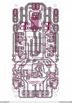
NAF , below is the "perfection" board.
the 5 pair version will be the same with 2 more OP pairs.
V1.1 has ....
1.single 8/10 pin/5mm pitch OPS/IPS euro-terminal can be used....
, 3 /3 pin , or /3 2 pin (nearly universal).
2. OPS emitter resistors can be Noble 12.5mm pitch/25mm ceramic/ or
18mm non-inductive (mount in 25mm resistor spots)
3.lots of "housekeeping" ... caps realigned (more clearance) - labeling.
After reading another thread , I will clarify ... the 3 pair version is for
up to 65V rails , the 5 pair version will be for( up to) 80V rails. 4R operation
on either will be dependant on OP selection and/or the rail voltage.
IPS's can be run with boosted supply (5-10V above OPS).
PS- I will also post the V1.1 5pair soon ... "the other thread" is "250W 8 R
amplifier" - My "wolverine" with a base stopperless EF3 and PCB errors.
OS
Attachments
Last edited:
Thank you very muchNAF , below is the "perfection" board.
the 5 pair version will be the same with 2 more OP pairs.
V1.1 has ....
1.single 8/10 pin/5mm pitch OPS/IPS euro-terminal can be used....
, 3 /3 pin , or /3 2 pin (nearly universal).
2. OPS emitter resistors can be Noble 12.5mm pitch/25mm ceramic/ or
18mm non-inductive (mount in 25mm resistor spots)
3.lots of "housekeeping" ... caps realigned (more clearance) - labeling.
After reading another thread , I will clarify ... the 3 pair version is for
up to 65V rails , the 5 pair version will be for( up to) 80V rails. 4R operation
on either will be dependant on OP selection and/or the rail voltage.
IPS's can be run with boosted supply (5-10V above OPS).
PS- I will also post the V1.1 5pair soon ... "the other thread" is "250W 8 R
amplifier" - My "wolverine" with a base stopperless EF3 and PCB errors.
OS
Hi ostriber i want to try this.NAF , below is the "perfection" board.
the 5 pair version will be the same with 2 more OP pairs.
V1.1 has ....
1.single 8/10 pin/5mm pitch OPS/IPS euro-terminal can be used....
, 3 /3 pin , or /3 2 pin (nearly universal).
2. OPS emitter resistors can be Noble 12.5mm pitch/25mm ceramic/ or
18mm non-inductive (mount in 25mm resistor spots)
3.lots of "housekeeping" ... caps realigned (more clearance) - labeling.
After reading another thread , I will clarify ... the 3 pair version is for
up to 65V rails , the 5 pair version will be for( up to) 80V rails. 4R operation
on either will be dependant on OP selection and/or the rail voltage.
IPS's can be run with boosted supply (5-10V above OPS).
PS- I will also post the V1.1 5pair soon ... "the other thread" is "250W 8 R
amplifier" - My "wolverine" with a base stopperless EF3 and PCB errors.
OS
I'm happy if you say where is the input board or boards?
Best regards.
Thimios.
With 3 pairs NJW @ 60V rails , the SOA curve says we can pulse 15-16A !
for the 25ms high current cycle of a 20hz waveform.
I would prefer to have something akin to Bonsai's latching overcurrent protect
just disconnect the speakers completely versus just temporarily limiting
(and corrupting) fidelity.
Those VI limiters are for "party amps" or commercial. For commercial , nowadays ....
They use an input limiter controlled by computer monitoring of the OPS/SMPS.
Crown "peakX" uses a pre-programmed ROM to monitor 100ms SOA and the
pulse width of the SMPS (PS current). Also lets you to monitor your whole rack (many amps)
in windows (each amp has a IP address).
My "ultimate version" .....The "Bonsai circuit"
will totally disconnect the speaker output with a short.
You mention a V/t type scheme , where an overcurrent
condition will "throttle down" the OPS's current.
The best way to do this would be to "cripple" the power supply or "throttle"
the input when a preset averaged current is exceeded.
I've seen a input (semi) muting circuit that does this. Instead of affecting
the OPS ... it just lowers the input level until the overload "passes".
This in concert with the "Bonsai protect" would match the crown scheme
without any digital "bloat". 😀
PS - we could average the Re voltage drop like you mention and
set a threshold (with an opto) to either a. lower input b. "cripple PS" or c. disconnect !
OS
I think I must put "Bonsai protect" as option on my PCB.
I am not sure about mosfet for speaker protection, because sometime I can not find it in local market. I should ask Naf or John Bali about it.
If I can not find the mosfet, what kind of relay that I must use for speaker protect? 10A, 20A, or 30A contact?
Last edited:
And for low power version, say 35v rails ?
Didiet
I think for 35V we can use single pair. But you can use more pair if you want. Drive 2 Ohm speaker, or to reduce the distortion a bit.
Hello Uncle Os,
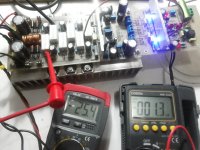
The leds were lit...
I set 60mA per pair
Stable dc offset 1.x mV necer reach 2mV
It's night here so i'm not connect it yet to my speaker.
But this Slewmaster was shown a good sign of stability no oscillation😎😉
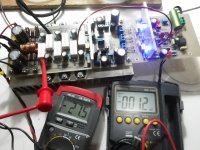
The leds were lit...
I set 60mA per pair
Stable dc offset 1.x mV necer reach 2mV
It's night here so i'm not connect it yet to my speaker.
But this Slewmaster was shown a good sign of stability no oscillation😎😉
Attachments
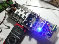
I reduced output to 2 output pairs because i only have 4 pairs mjll21193-4 for a stereo version and with lower supply voltage and mje1503x drivers.hope its ok.
Attachments
Last edited:
Hello Uncle Os,
The leds were lit...
I set 60mA per pair
Stable dc offset 1.x mV necer reach 2mV
It's night here so i'm not connect it yet to my speaker.
But this Slewmaster was shown a good sign of stability no oscillation😎😉
Servo is neat , aye ! Actively adjusts the offset...
Are they blue or UV leds ?
How is OPS thermal stability with the NJWxxxx drivers/Vbe ? this was the only
"guess of mine" .. 😀 I simulated with mje340/350 - NJW-NJW (pre/driver/OP)
for OPS circuit.
Nice to have something run the first time .... that is why I don't let the
computer do my layout , do the layout in "sections" (OPS/Vbe/multipliers).
Good work !!
OS
I reduced output to 2 output pairs because i only have 4 pairs mjll21193-4 for a stereo version and with lower supply voltage and mje1503x drivers.hope its ok.
Go for it ... the more the merrier !! 🙂
PS- edit the V1.1 OPS - then we can standardize troubleshooting/
layout issues. It is slightly better (shorter traces/more verbose).
See the "ghost resistor" error -V1.0 !!!! use V1.1 ... PERFECT !
In fact , you can contribute the 2 pair version - some want lower rail V/wattage !!
OS
Last edited:
I have a theoretical question about this type of design. Given a maximum output of 60watts at 4ohms and driven at the worst case power level, whether 1/3 power or what creates maximum dissipation with music as an input, and a heat sink size of 16" x 4" with 1" tall fins could someone give me an idea of what the internal heat production would be inside a plastic non conductive enclosure? The 16" dimension is the vertical dimension of the heat sink. The internal air space is about 1/2 to 1/3 of a cubic foot.
I have a theoretical question about this type of design. Given a maximum output of 60watts at 4ohms and driven at the worst case power level, whether 1/3 power or what creates maximum dissipation with music as an input, and a heat sink size of 16" x 4" with 1" tall fins could someone give me an idea of what the internal heat production would be inside a plastic non conductive enclosure? The 16" dimension is the vertical dimension of the heat sink. The internal air space is about 1/2 to 1/3 of a cubic foot.
That's a lot of variable's , man !!
I do know the 16 X 4 X 1" HS would be
sufficient for the 3 or 5 pair slewmaster.
The IPS and drivers on the OPS would produce minimal heat , most of the
heat would be conducted to the main HS.
At 60W 8/4R , the 3 pair "slew" would be at "idle" (would not break a sweat)
The only way to really know (with all those variables) is to actually build it. 😀
PS - OP devices can determine the heat generated as well ... sanken planar devices can
be biased as low as 15-30ma/device (very small heatsinks).
OS
I have a theoretical question about this type of design. Given a maximum output of 60watts at 4ohms and driven at the worst case power level, whether 1/3 power or what creates maximum dissipation with music as an input, and a heat sink size of 16" x 4" with 1" tall fins could someone give me an idea of what the internal heat production would be inside a plastic non conductive enclosure? The 16" dimension is the vertical dimension of the heat sink. The internal air space is about 1/2 to 1/3 of a cubic foot.
Ill defined problem.
A non conductive plastic case means an adiabatic enclosure, that is, which doesn't exchange heat with the outside? Or is the plastic non conducting case perforated, so that it is vented?
What do you mean by "what the internal heat production would be inside a plastic non conductive enclosure"? Perhaps you mean the temperature? Heat # temperature.
Such problems barely have exact, analytic answers, but more likely engineering estimated solutions. For example, if the plastic non conductive case of a certain size is "transparent" to air flows (that is, the air can freely flow, naturally or forced, over the heat sink), then the case material is of a less importance. Plastic vs. metal, would only lack the conduction component, which is low compared to convection heat dissipation.
There are engineering diagrams to design the air flows and the thermal layouts in a case, sorry I don't have any reference at hand.
- Home
- Amplifiers
- Solid State
- Slewmaster - CFA vs. VFA "Rumble"