The crossover is pretty much ready for etching. Do you have any suggested reading for a DA converter?
Luke, use the force....
I tried it once. The HK990 had toslink. No hum , no noise. luckily
I had an E-waste 3' toslink. Clicked the digital out -toslink soundcard checkbox ...
the HK's digital indicator lit up - music !!
Yes - the force (21st century audio).
OS
The crossover is pretty much ready for etching. Do you have any suggested reading for a DA converter?
Many dacs out there.
some have built - in toslink , all have S/PDIF.
SP and toslink are the same format - one is light, one is electrical.
They make toslink to spdif convertor kits (10$).
So , any DAC would work.
Many of the "pocket DAC's" are toslink capable and can be had
for <50$. Only 95db noise on these cheepies. 🙁
In kit form , 50$-150$ gets you a TDA1541 to a ESS90xx -
with or without toslink (get the adaptor). >125db noise/192khz ...
puts the best creative/ASUS D/A convertors to shame.
edit- with burr-brown ADxx op-amps , a good DAC has 1-2ppm
THD. ONLY source that can pull this off.
OS
Last edited:
I've got one of China's finest on it's way. I have no idea what the output voltage is going to be.
Grounding and AC issues.Sounds excellent but I can hear my mouse scroll wheel through the speakers. Any idea why these are so sensitive?
Too, see if, there is not too much volts between grounds of the various elements of your reproducing system when not connected together. Find the AC plugs senses witch produce the less V.
Last edited:
Tda 1541 dac with discrete op out, driven spdif koax in, totaly dead and quiet.Very dynamic combination,non over sampling 1541 naturaly.
Tda 1541 dac with discrete op out, driven spdif koax in, totaly dead and quiet.Very dynamic combination,non over sampling 1541 naturaly.
TDAxxxx is last generation 16bit DAC tech.
Prices have come down - (below) there's a whole display/32bit AK4399 (32bit)
- <70$ !!
Or - CS4398's are dime a dozen <50$ (24 bit).
Have my "beast" amp totally silent !!😀 Was never able to get my OEM's this
silent with a PC hookup. That -123db AK4399 is looking real enticing
There is still some noise ... the ksa/c input pairs. I suspect (and really so) that
the BC550/560's are a quieter breed of semi. Their models show 1/3 the
nanovolt residual with zero input , as opposed to the ksa/c's.
Kypton ND's diamond will be the first slew with first stage BCxxx's.
OS
Attachments
Have you got your input factory up and running? When's the Kypton-ND test drive?
Of course , I just wanted to let the others "steal the show" for a while.
Val , Dadod , apex , and others all come up with good ideas (then I integrate
them). That's how it works around here.
I actually have the bootstrap IPS , symetri , kypton ND , val's "one fet wonder"
and a symmetric (1ppm) line stage all ready for sprint.
When I go - I like to do a "series" of designs.
Look back - you will see this .....
Edit - I'm absorbing my study of the electrical /thermals in my real amps to apply
to the new series. Should be even more "tight" than before.
OS
Last edited:
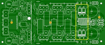
hey guys I have a question on the power supply input area I notice the 4 MUR460 diodes that can be use on other audio amplifiers ? and if you don't mind guys can some one explain what are the purpose of those diodes on the circuit sorry for the silly question 🙂
I'm guessing is sort of like a protection I think 🙄
Regards
Juan
I'm guessing is sort of like a protection I think 🙄
Regards
Juan
Attachments
hey guys I have a question on the power supply input area I notice the 4 MUR460 diodes that can be use on other audio amplifiers ? and if you don't mind guys can some one explain what are the purpose of those diodes on the circuit sorry for the silly question 🙂
I'm guessing is sort of like a protection I think 🙄
Regards
Juan
Hi Juan,
The diodes are a sort of protection.
One pair protects against incorrect polarity damaging the amplifier. The idea being the rail fuse should blow and the worst case would be a shorted diode, though they are pretty tough and would usually survive.
The other pair are sometimes called 'catching' diodes and prevent reactive loads like real speakers and crossovers from being able to back-feed to the rails. In theory a wicked load and the right signal could send a pulse back that would be twice the rail, though such a situation is highly unlikely in reality.
Both could be considered optional, but for a few inexpensive diodes you get a somewhat more hardened and fool-proof design without any notable drawback.
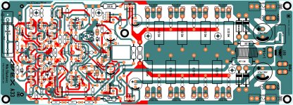
thanks you for the explanation 🙂 I was really curious if I can use that on this layout I think it does not hurt at all if I use it, I apologize if this is not a slew master subject but the diodes safe features from slew master I'm really interested in incorporate that into this design, to be honest this is the first time I'm making a double side PCB and not using any jumpers lol, thanks again 🙂
Regards
Juan
Attachments
Last edited:
thanks you for the explanation 🙂 I was really curious if I can use that on this layout I think it does not hurt at all if I use it, I apologize if this is not a slew master subject but the diodes safe features from slew master I'm really interested in incorporate that into this design, to be honest this is the first time I'm making a double side PCB and not using any jumpers lol, thanks again 🙂
Regards
Juan
Look MUCH closer at the slew , Vargas. without the ground taps right DEAD
CENTER - and a tap from this exact point for the input stage ground , you
will take Apex's design from phenomenal to just good.
Alex mm does not really get it . Myself , john curl , and Pass do (looking at
parasound and pass labs designs).
To get a real > -115db S/N is harder than you might think !!
OS
> -115db S/N (and lower).
As I said , hard to get.
My H/K 680 - only -107db
-pass X250 -117db
-parasound hca2200 -115db
Curl and Pass must have a secret ?
Can the lowly Slew be brought to this level ? How can you hear noise and
hum lower than the speaker can reproduce ? (Headphones)
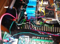
First , (below #1 in photo)
All chassis parts , the 35A bridge ground loop breaker and any RF filtering -
go to a direct chassis star. (that must hook to a real earth ground).
The loop breaker will have a paralleled 10R/1W and .01uF cap to pass
(isolated ground) RF to earth.
From that loop breaker , the green wire (#2 in photo) connects to an isolated star.
Here , you use a plastic washer , put 2 layers of heat tubing around a 6mm bolt
going through a 7mm hole and place another insulator at top (FR-4 shown).
To this star connect all capacitor returns , OPS /speaker returns.
Splitting the isolated / chassis direct grounds was the "trick". Not only was I
below loudspeaker detectable, but I am at the headphone level (barely detectable).
Toroid induced fields are also a consideration with a tight "package" (my amp).
Any auxiliary circuitry should either have a floating ground (or referenced through
a lift resistor). Isolating my protection circuits ground was another "milestone".
Screws and any metal part near the toroid generate minute voltages that WILL
affect a sensitive amp. 😱
With these "tricks" ... all worked out , I now have my 10K$ amp. Most likely
specs out the same or better than the parasound/pass.
PS - this grounding even "absorbs" a formerly chronic ground loop. a-mazing.
Can't do this stuff with LT spice !!!
Edit - this had to be done to continue with ppm IPS's that are capable of -120db
noise levels !!!
OS
As I said , hard to get.
My H/K 680 - only -107db
-pass X250 -117db
-parasound hca2200 -115db
Curl and Pass must have a secret ?
Can the lowly Slew be brought to this level ? How can you hear noise and
hum lower than the speaker can reproduce ? (Headphones)
First , (below #1 in photo)
All chassis parts , the 35A bridge ground loop breaker and any RF filtering -
go to a direct chassis star. (that must hook to a real earth ground).
The loop breaker will have a paralleled 10R/1W and .01uF cap to pass
(isolated ground) RF to earth.
From that loop breaker , the green wire (#2 in photo) connects to an isolated star.
Here , you use a plastic washer , put 2 layers of heat tubing around a 6mm bolt
going through a 7mm hole and place another insulator at top (FR-4 shown).
To this star connect all capacitor returns , OPS /speaker returns.
Splitting the isolated / chassis direct grounds was the "trick". Not only was I
below loudspeaker detectable, but I am at the headphone level (barely detectable).
Toroid induced fields are also a consideration with a tight "package" (my amp).
Any auxiliary circuitry should either have a floating ground (or referenced through
a lift resistor). Isolating my protection circuits ground was another "milestone".
Screws and any metal part near the toroid generate minute voltages that WILL
affect a sensitive amp. 😱
With these "tricks" ... all worked out , I now have my 10K$ amp. Most likely
specs out the same or better than the parasound/pass.
PS - this grounding even "absorbs" a formerly chronic ground loop. a-mazing.
Can't do this stuff with LT spice !!!
Edit - this had to be done to continue with ppm IPS's that are capable of -120db
noise levels !!!
OS
Attachments
That's how mine's hooked up but I'm still getting a little 60hz. I've got to track that down this weekend.
That's how mine's hooked up but I'm still getting a little 60hz. I've got to track that down this weekend.
The old way , with my 88db small speakers - heard nothing.
My 91db daytons - I heard it (faintly). So , I decided to see how far (low)
I could go. Even washing my spooks and kyptons in alcohol and
a toothbrush (flux residuals) reduced the noise.
Stuff sitting topside of my toroid are getting residual EMF. Val's protection
circuit has not even hiccuped , despite this fact.
Very satisfied now.
PS - I'm sure you will get yours to this level (WAY beyond OEM)😀
OS
Hum... You and yourself ?Alex mm does not really get it . Myself , john curl , and Pass do
OS
Can you tell me please if that heatsink for the drivers at your's OPS for BJT gets much warm ?
I have to make very small OPS boards and I can not decide which way to go, drivers on the main or separate heatsink --> I have only 60mm of width to make PCB
THX
Peter
Can you tell me please if that heatsink for the drivers at your's OPS for BJT gets much warm ?
I have to make very small OPS boards and I can not decide which way to go, drivers on the main or separate heatsink --> I have only 60mm of width to make PCB
THX
Peter
OS
Can you tell me please if that heatsink for the drivers at your's OPS for BJT gets much warm ?
I have to make very small OPS boards and I can not decide which way to go, drivers on the main or separate heatsink --> I have only 60mm of width to make PCB
THX
Peter
Way cooler than the main heatsinks , even in the case..
About the same as the VAS heatsink.
Shaking the house - just a little warmer.
Edit - I use 150 driver Re. HK680 uses 220R and NO heatsink.
OS
- Home
- Amplifiers
- Solid State
- Slewmaster - CFA vs. VFA "Rumble"