Add the super - pair = 5ppm + good clip.
Nothing else changes , except for rounded edges. 🙂
(below 1/2).
PS - built either way , 5 or 8 ppm (what's the difference?).
Still ... a "jewel".
edit- everything still is VERY dependent on Q1/2. TO-92L would be the best
bet to get a "fault tolerant" design ( 12ma "bursts" with overload).
An inherent design deficiency that is unavoidable.
OS
Hi OS,
Try to increase source impedance and see how it could influence DC offset(DC servo functioning) and distortion.
I don't use a DC servo connected via input CCSs any more.
Damir
PS. Esperado's advice is good.
Last edited:
So is Keantoken's 😀 His comment and sim made me think and figure out why I at that time got a little THD improvement from adding them. I had 'fallen' for the same 'mistake' as Ostripper did: Trying to compensate for the Hawksford cascode rail current when used with a current mirror, by adjusting the emitter resistor of the mirror output device. I now removed those two transistors and if you consider going from 10 to 8 a 20% improvement, then yeah I stand delightfully corrected 🙂 I was already using a Wilson CM, and in the earliest versions I was indeed sinking the cascode rail into an adjusted emitter resistor -.- It appears that connecting the rail between the two stacked Wilson devices offers the best improvement.
Neither me.Hi OS,
I don't use a DC servo connected via input CCSs any more.
Looks cool on schematics, but, in fact, the noise will be higher as well as distortion.
(Too lazy to explain, think modulated current and unbalance).
There is NO added noise to avoid applying servo at feedback point if you set servo gain enough so the out can be attenuated enough by the serial resistance (in my amp output attenuated around 52db, with a low n noise OPA, imagine ;-)).
Last edited:
I like folding over the currents via wilson mirrors, this way VAS current is kept under control and will not wander with thermals. I too use the diamond input, this allows for impedance independent input filtering.
I too inject servo currents same place as feedback injection, I use two opamps and have a third order filter.
I too inject servo currents same place as feedback injection, I use two opamps and have a third order filter.
According to my previous demonstration (DVSSA), this (in red) has to be avoided (on my opinion).
Can-you measure distortion @ 50Hz ?
Does not seem to be a issue with this one .... 🙂 (below 1)
-amp has 90db+ CLG @ 50hz.
I don't like caps , either .... but it is the simple way out.
Looks cool on schematics, but, in fact, the noise will be higher as well as distortion.
(Too lazy to explain, think modulated current and unbalance).
There is NO added noise to avoid applying servo at feedback point if you set servo gain enough so the out can be attenuated enough by the serial resistance (in my amp output attenuated around 52db, with a low n noise OPA, imagine ;-)).
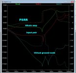
This also does not seem to be a issue. The floating virtual ground decoupled
with the op-amp as the source gives quite the PSSR at that point (below 2-
blue plot).
The red plot-below2- is the input pair PSRR. CFA-X was worse using the
red LED CCS's.
I might "fine tune" the Servo , as it is the main player in total PSSR.
How can I complain about 4-8ppm (20-20K) ?
(below 3 - 20K) same as 50hz ? Lots of gain margin !
OS
Attachments
Both feet in the stating blocks. Just waiting on a PCB design. Seems OS and Jason are working on getting the layouts completed. I just finished getting a pair of Apex Studio Reference boards working. It was quite an effort due to poor quality etching and boards. Looking forward to getting back to board house boards.
Blessings, Terry
Blessings, Terry
Both feet in the stating blocks. Just waiting on a PCB design. Seems OS and Jason are working on getting the layouts completed. I just finished getting a pair of Apex Studio Reference boards working. It was quite an effort due to poor quality etching and boards. Looking forward to getting back to board house boards.
Blessings, Terry
Kypton-V is very similar to APEX's creation(s). I simulated both of
apex's baxandall amps. Not bad , at 60-100ppm.
BUT !!! not good enough. It should be as (below).
No reason why it should not be as good as the wolverine !
All that CLG (below 2) - no reason for >10ppm.
OS
Attachments

The 'Eyesee' project is the one that has me twitchy. I have grown fascinated by simple elegance in my old age.
Does not seem to be a issue with this one .... 🙂 (below 1)
-amp has 90db+ CLG @ 50hz.
I don't like caps , either .... but it is the simple way out.
This also does not seem to be a issue. The floating virtual ground decoupled
with the op-amp as the source gives quite the PSSR at that point (below 2-
blue plot).
The red plot-below2- is the input pair PSRR. CFA-X was worse using the
red LED CCS's.
I might "fine tune" the Servo , as it is the main player in total PSSR.
How can I complain about 4-8ppm (20-20K) ?
(below 3 - 20K) same as 50hz ? Lots of gain margin !
OS
Hi Os, I simulated LG with simple voltage probe (as in your .asc file) and with Tian probe and here is the result, no big difference, but I don't understand the LG increase after 4 MHz, and very low GM.
Did you get similar result?
dado
Attachments

Consider that the input mirror's node is driven from the op-amp.
That is another reason I decoupled the op-amp output with a 10uF.
Probing the op-amp shows those same little dips/spikes at 4/13mhz.
Even as this might be "blasphemy" (op-amp corrupting the milk) ,this
CFA variant beats the rest easily.
I used BV's CFB summed cap trick , the NAD single MIC ,
Miib's floating mirror's ,and the OS/vzaichenko VAS. "abomination like"😀
OS
I don't know how it was possible but World of Warcraft is now related to DIY Audio 😛 Does it sound and look like Patchwerk?I used BV's CFB summed cap trick , the NAD single MIC ,
Miib's floating mirror's ,and the OS/vzaichenko VAS. "abomination like"😀
OS
Consider that the input mirror's node is driven from the op-amp.
That is another reason I decoupled the op-amp output with a 10uF.
Probing the op-amp shows those same little dips/spikes at 4/13mhz.
Even as this might be "blasphemy" (op-amp corrupting the milk) ,this
CFA variant beats the rest easily.
I used BV's CFB summed cap trick , the NAD single MIC ,
Miib's floating mirror's ,and the OS/vzaichenko VAS. "abomination like"😀
OS
When I disconnect the DC servo amp, the LG looked the same.
Damir
Where did you get these models?Have you guys tried these?
.MODEL 2SK1058 NMOS (VTO=403.969M KP=20U L=2U W=29.7482M GAMMA=0 PHI=600M
+ LAMBDA=184.988F RD=60.8251M CBD=2.56138N IS=10F CGSO=1.13517N CGDO=1.13517N
+ TOX=0 NSUB=0 TPG=1 UO=600 RG=50 RDS=1MEG )
.MODEL 2SJ162 PMOS (VTO=842.193M KP=20U L=2U W=21.3317M GAMMA=0 PHI=600M
+ LAMBDA=20.7067M RD=837.199M CBD=2.96862N IS=10F CGSO=1.13517N CGDO=1.13517N
+ TOX=0 NSUB=0 TPG=1 UO=600 RG=50 RDS=1MEG )
.MODEL ECX10N16 NMOS (LEVEL=1 VTO=-66.415M KP=20U L=2U W=76.3794M GAMMA=0
+ PHI=600M LAMBDA=3.44617M RD=244.181M RS=178.517M IS=10F CGSO=100P CGDO=100P
+ TOX=0 NSUB=0 TPG=1 UO=600 KAPPA=200M RG=367.902 RDS=16.0012K )
.MODEL ECX10P16 PMOS (LEVEL=1 VTO=56.1959M KP=20U L=2U W=49.9039M GAMMA=0
+ PHI=600M LAMBDA=16.6941M RD=458.28M RS=214.674M CBD=1.00674N IS=10F CGSO=100P
+ CGDO=100P TOX=0 NSUB=0 TPG=1 UO=600 KAPPA=200M RG=35.8793 RDS=1MEG )
Where did you get these models?
A text file downloaded from here. I'm attaching it.
Attachments
When I disconnect the DC servo amp, the LG looked the same.
Damir
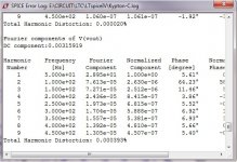
Well ,I tweaked the servo anyways. 24db/oct dropped 20Hz thd to 1ppm!
(50hz is 3ppm) - no problem at low frequencies. 😀
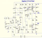
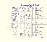
Both the Kypton V/C are in the finalized stage. Both do 2ppm 20hz - 6ppm
20K , have low offset .... and can "eat them square-waves". 🙂
PS - the "V" is now a symmetrical level -shifted Baxandall/Hawksford with a
wolverine (blameless) front end.
If there is interest , I WILL make toner transfer IPS's.
OS
Attachments
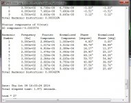
Sorry I took my time ... "no fine wine before it's time". 😀
These simulations not only will "eat square-waves" , but you can ....
1.swap any model into them.
2.perform better than my last generation of IPS's.
Single digit PPM -all the way
The "V" is actually better than the wolverine. At 2+ volt input ,
It is still 6ppm @ 20K.
This is attributed to the (Q10/Q12) buffers for the super-pairs. (below 1/2)
NO LOAD on the current mirrors , better than the typical Doug Self
beta enhanced VAS.
Mr. Self says a symmetrical VAS is inferior to a current sourced one. BS !!
"V" is a "gain monster" with good PM. Very stable.
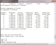
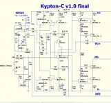
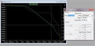
On the "C" , I get very good results with 1 cap (MIC) to the CFB node.
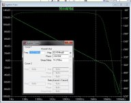
But ... phase margin is less. CFA margin does not have to be as much for
stability. A second option is to add 2- 27pF millers on the VAS (below 3).
Less unity gain freq. , but more PM.
The "C" still can't do 6 ppm at 2 volt input , even with the same 12db
gain margin at 20Khz. I'll add both options to the PCB. 🙂
PS-I noticed more people looked at the "C" than the "V" above.😱
They is "racist" against the VFA .... geeez !😀
OS
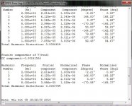
edit - (below 4) is what is different about the "C". - much higher CLG.
These simulations not only will "eat square-waves" , but you can ....
1.swap any model into them.
2.perform better than my last generation of IPS's.
Single digit PPM -all the way
The "V" is actually better than the wolverine. At 2+ volt input ,
It is still 6ppm @ 20K.
This is attributed to the (Q10/Q12) buffers for the super-pairs. (below 1/2)
NO LOAD on the current mirrors , better than the typical Doug Self
beta enhanced VAS.
Mr. Self says a symmetrical VAS is inferior to a current sourced one. BS !!
"V" is a "gain monster" with good PM. Very stable.
On the "C" , I get very good results with 1 cap (MIC) to the CFB node.
But ... phase margin is less. CFA margin does not have to be as much for
stability. A second option is to add 2- 27pF millers on the VAS (below 3).
Less unity gain freq. , but more PM.
The "C" still can't do 6 ppm at 2 volt input , even with the same 12db
gain margin at 20Khz. I'll add both options to the PCB. 🙂
PS-I noticed more people looked at the "C" than the "V" above.😱
They is "racist" against the VFA .... geeez !😀
OS
edit - (below 4) is what is different about the "C". - much higher CLG.
Attachments

Last edited:
Where did you get these models?
They are NMOS level 1 models, so the gate currents won't be accurate nor will behavior in the crossover region.
Use Cordell's models, AFAIK anything else will just be misleading.
They are NMOS level 1 models, so the gate currents won't be accurate nor will behavior in the crossover region.
Use Cordell's models, AFAIK anything else will just be misleading.
I know very little about spice. Learning as I go. I do have a question for you. Have you compared the models in the file I attached against the real transistors? Have you tried the Cordell models against the real transistors?
Thanks, Terry
- Home
- Amplifiers
- Solid State
- Slewmaster - CFA vs. VFA "Rumble"