A bit like using a cello to play a violin part, in my opinion.
About paralleling FETs, what about this neat idea of Mooly ?
http://www.diyaudio.com/forums/solid-state/240712-cfa-topology-audio-amplifiers-218.html#post3801258
About paralleling FETs, what about this neat idea of Mooly ?
http://www.diyaudio.com/forums/solid-state/240712-cfa-topology-audio-amplifiers-218.html#post3801258
Please, consider that Laterals like to run at 100-150mA of quiescent.(Each !)
Do you really want 500-750 ma ?
With multiple units, you will probably need more current margin, because of their disparities if not perfectly matched.
Parasitic gate capacitances will probably increase in such a arrangement, making them harder to drive at HF.
Personally I've never used more than two laterals in my amps.
I'm laying out an output board to accept up to 5 output pairs. Only populate as many as desired. 750 ma? I think my tv idles more current than that.
Sorry for small off-topic, I have lack of knowledge and need some advice.
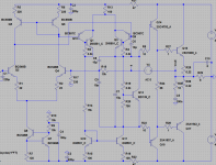
I have drawn Hitachi VAS with CFP configuration of the differential pair it seems to have very high input impedance and lot of gain but I do not know if this is good idea to use that kind of VAS?
Thanks a lot.
I have drawn Hitachi VAS with CFP configuration of the differential pair it seems to have very high input impedance and lot of gain but I do not know if this is good idea to use that kind of VAS?
Thanks a lot.
Attachments
Sorry for small off-topic, I have lack of knowledge and need some advice.
I have drawn Hitachi VAS with CFP configuration of the differential pair it seems to have very high input impedance and lot of gain but I do not know if this is good idea to use that kind of VAS?
Thanks a lot.
That type of VAS is "shaky" even with plain beta enhancement. For more
gain , I was thinking more like a cascoded superpair .... in this application.
(look to the "symasui") cascodes = low vce active devices.
OS
Helper
Hi Borys, looks cool, just one comment. Having input LTP equipped with both CCS at the bottom and current mirror at the top, makes VAS quiescent current somewhat "undetermined", so practical implementation may suffer some VAS current fluctuations.
Adding helper transistor will stabilize it - see my example - Q6, R9, R11 >HERE<
Cheers,
Valery
P.S. Wrote at the same time with OS 🙂 Good point as well 😉
Sorry for small off-topic, I have lack of knowledge and need some advice.
I have drawn Hitachi VAS with CFP configuration of the differential pair it seems to have very high input impedance and lot of gain but I do not know if this is good idea to use that kind of VAS?
Thanks a lot.
Hi Borys, looks cool, just one comment. Having input LTP equipped with both CCS at the bottom and current mirror at the top, makes VAS quiescent current somewhat "undetermined", so practical implementation may suffer some VAS current fluctuations.
Adding helper transistor will stabilize it - see my example - Q6, R9, R11 >HERE<
Cheers,
Valery
P.S. Wrote at the same time with OS 🙂 Good point as well 😉
Last edited:
Hi Borys, looks cool, just one comment. Having input LTP equipped with both CCS at the bottom and current mirror at the top, makes VAS quiescent current somewhat "undetermined", so practical implementation may suffer some VAS current fluctuations.
Adding helper transistor will stabilize it - see my example - Q6, R9, R11 >HERE<
Cheers,
Valery
P.S. Wrote at the same time with OS 🙂 Good point as well 😉
Valery, this his not true for Borys circuit, but it is for yours(complementary differential input stage).
Damir
Hi Damir, right, for complimentary it is, let say, mandatory, but in this particular case also makes a lot of sense.
Imagine, IPS is fully balanced. Then, potentials at the base and at the collector of Q5 (schematic above) will tend to zero-out, putting Q5 in difficult conditions (close-to-zero c-b). Adding a helper, adds Vbe to the right shoulder, allowing some 0.7V for Q5's c-b and making the whole thing much more stable DC-wise. BC5XX is a good choice for the current mirror, as even with those 0.7V, some transistors will not feel good there, but BC5XX will 🙂
Cheers,
Valery
Hi Damir, right, for complimentary it is, let say, mandatory, but in this particular case also makes a lot of sense.
Imagine, IPS is fully balanced. Then, potentials at the base and at the collector of Q5 (schematic above) will tend to zero-out, putting Q5 in difficult conditions (close-to-zero c-b). Adding a helper, adds Vbe to the right shoulder, allowing some 0.7V for Q5's c-b and making the whole thing much more stable DC-wise. BC5XX is a good choice for the current mirror, as even with those 0.7V, some transistors will not feel good there, but BC5XX will 🙂
Cheers,
Valery
Valery, I noticed that all English native speaker write complimentary instead complementary, but I am surprised that you rusky do the same.
For us Slavic speakers compliment and complement sound different, not the same as for English native speakers.
Damir
Valery, I noticed that all English native speaker write complimentary instead complementary, but I am surprised that you rusky do the same.
For us Slavic speakers compliment and complement sound different, not the same as for English native speakers.
Damir
You're right! 😀
Well, the meaning is different, but the sounding is very similar - that's where the mistake comes from 🙄
THANKS for explenation, my learning process is slow but going forward anyway.
I didn't found the key to the perfect sounding amp so far but I found that they may sound different even if they are looking the same on the ''paper''.
BIG thanks.Peter
I didn't found the key to the perfect sounding amp so far but I found that they may sound different even if they are looking the same on the ''paper''.
BIG thanks.Peter
new stuff / old stuff = more IPS's
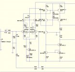
A few more tinkering(s).
One does 15ppm,the other .... 8 .
First is - "badger/wolverine" meets hawksford/ baxandall.
Second is a folded cascode ...(Roender , abomination , havoc)
Might they sound different ??
OS
A few more tinkering(s).
One does 15ppm,the other .... 8 .
First is - "badger/wolverine" meets hawksford/ baxandall.
Second is a folded cascode ...(Roender , abomination , havoc)
Might they sound different ??
OS
Attachments

Just if it can help some of you to figure out the pros and cons of adding a driver after a VAS, or any additional pole, and looking at its input ( a tip that i recommend) in my DDSSA, the frequency where the bandwidth increase of 3dB (in connection with the open loop bandwidth) goes from 9KHz with DVSSA to 7KHz for the DDSSA. Means less feedback ratio (more distortion) at 10KHz.
In a ideal audio world, with devices offering a transition frequency faster than our poor 100MHz ;-), it should be flat up to 20Kz , or, at least 10KHz if we consider 19KHz as our audibility limit (harmonic 2).
In a ideal audio world, with devices offering a transition frequency faster than our poor 100MHz ;-), it should be flat up to 20Kz , or, at least 10KHz if we consider 19KHz as our audibility limit (harmonic 2).
I'm going with the "Kypton's"
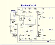
Kypton-C (below 1)
.. is a "jewel" (vssa/CFA-X) with all the "toy" like issues solved.
-90db psrr.
-8 ppm.
-servo without DC NFB.
- cool running with 4 red LED's.
- simple 12 device unit with 1 comp. path. (MIC)
I like it.
My last posted "Kypton" is the V (VFA amp).
Apex amp with 20X less thd and good clipping .. 3ppm.
Actually beats the "wolverine" 😱 .
The "C" can go as low as 1ppm if you replace the simple mirrors
with wilson mirrors. The drawback is loss of (a little)voltage swing at
the hawksford (1 more led !!). But , you will have a unique "wilson/hawksford".
PS - slew is "king" .. bandwidth can go as high as 4mhz (PM is less). 😀
Edit - ahhhh - CLG on this CFA is 90db+ @ 1K ... like a VFA !
OS
Attachments

Last edited:
I have a trick for your hawksford cascode that makes that particular combo (current mirror + H-cascode) perform even better. Add Q26 in the diagram below 😀 (Do the same on the bottom end).
I've accustomed myself to call the upper circuit half of an amp the "North" side, the lower half the "South" side. So yeah, add the transistor to the south side of the cascode also.
Edit: Oh yeah, you can equalize R14/R15 again in your schematic after adding this little mod 🙂
I've accustomed myself to call the upper circuit half of an amp the "North" side, the lower half the "South" side. So yeah, add the transistor to the south side of the cascode also.
Edit: Oh yeah, you can equalize R14/R15 again in your schematic after adding this little mod 🙂
Attachments

Last edited:
In what way does it perform better? You defeat the base-recirculation loop, which in my simulations reduces CCS output impedance by more than 10 times. Output impedance is generally the main reason to use base recirculation.
The cascode Ib is prevented from flowing through the VAS transistor, so this eliminates one of the last sources of load-independent distortion for this VAS.
However we still have the problem that the base currents of the cascode flow through the VAS, which is unnecessary and lets some distortion through. The version on the right does better from a THD, gain, speed and phase standpoint, without sacrificing 20db of output impedance.
Attachments

Last edited:
It is a "jewel" ...
Add the super - pair = 5ppm + good clip.
Nothing else changes , except for rounded edges. 🙂
(below 1/2).
PS - built either way , 5 or 8 ppm (what's the difference?).
Still ... a "jewel".
edit- everything still is VERY dependent on Q1/2. TO-92L would be the best
bet to get a "fault tolerant" design ( 12ma "bursts" with overload).
An inherent design deficiency that is unavoidable.
OS
Attachments
Last edited:
A good jewel case is needed for jewels.....go ahead for a good made PCBAdd the super - pair = 5ppm + good clip.
Nothing else changes , except for rounded edges. 🙂
(below 1/2).
PS - built either way , 5 or 8 ppm (what's the difference?).
Still ... a "jewel".
edit- everything still is VERY dependent on Q1/2. TO-92L would be the best
bet to get a "fault tolerant" design ( 12ma "bursts" with overload).
An inherent design deficiency that is unavoidable.
OS
Last edited:
jewell impurities
According to my previous demonstration (DVSSA), this (in red) has to be avoided (on my opinion).
Can-you measure distortion @ 50Hz ?
According to my previous demonstration (DVSSA), this (in red) has to be avoided (on my opinion).
Can-you measure distortion @ 50Hz ?
Attachments

Last edited:
Now what if you change the cascoded device (which you set by a series of diodes) into a current mirror? The improvement from the additional transistor may be a result of linearizing the current mirror again. When you let the cascode reference loop sink into the current mirror emitter resistor, this additional current severely affects current mirror linearity.In what way does it perform better? You defeat the base-recirculation loop, which in my simulations reduces CCS output impedance by more than 10 times. Output impedance is generally the main reason to use base recirculation.
The cascode Ib is prevented from flowing through the VAS transistor, so this eliminates one of the last sources of load-independent distortion for this VAS.
However we still have the problem that the base currents of the cascode flow through the VAS, which is unnecessary and lets some distortion through. The version on the right does better from a THD, gain, speed and phase standpoint, without sacrificing 20db of output impedance.
Edit: I'll give your version a try as well, might be well that yours works even better as it also avoids the reference rail sinking into the mirror itself, which was the main reason for adding that transistor.
Last edited:
Useful update: It's the actual equalizing of the current mirror emitter resistors that caused the improvements (in THD). Ofcourse obviously, but in Ostripper's schematic he has offset them to deal with the cascode reference rail current, to keep the VAS current an actual 1:1 mirror. But that worsens THD a lot. From then on, I went to compare between with and without that extra transistor. Adding it makes THD worse. In fact between these two, sinking the cascode rail into the CM is the better option and one should not offset the mirror emitter resistors and instead maintain a different thinking as the mirror output current is shared between the VAS rail and the cascode rail: I(in)=I(vas)+I(cascoderail). This however, is by using a Wilson mirror, the cascrail is injected into the collector of the Wilson cascoded device. Sinking into the emitter resistor directly I haven't tested yet.
Edit: Ok. Sinking directly into the emitter resistor makes THD go BAD. Offsetting the resistor to make the voltages across them equal again improves the BAD some, but not by much and it's still bad. Throw in that 3rd tranny and make a Wilson CM indeed 😀 Then, sinking the cascode rail into the junction that connects the mirror bases, has no impact on mirror performance. You're just splitting the mirror output into two rails in the end.
Edit: Ok. Sinking directly into the emitter resistor makes THD go BAD. Offsetting the resistor to make the voltages across them equal again improves the BAD some, but not by much and it's still bad. Throw in that 3rd tranny and make a Wilson CM indeed 😀 Then, sinking the cascode rail into the junction that connects the mirror bases, has no impact on mirror performance. You're just splitting the mirror output into two rails in the end.
Last edited:
- Home
- Amplifiers
- Solid State
- Slewmaster - CFA vs. VFA "Rumble"