3 pair BJT = 150W/8R , my favorite range. "Slewmonster" can have just
3 pair .. better thermal distribution.
OTOH , 3 pair IRFP-FET is a 400W beast. If only they were more "audio friendly".
HEC might facilitate this.
OS
How is it that the IRFP are 3X the power of MJL? Can you explain that a little more?
Thanks, Terry
Hi, Dadod,It was to good to be true, so I simulate it using Cordell modes real CCS and bias spreader. My simulations were far from yours, SR and distortion.
That the second time (*) you made such a remark about one of my sims.
I don't understand (and don't believe in sims as well, specially about power mosfets) while i'm, for sure, not an expert in simulations.
On my ASC is: ".include cordell-models.txt".
Replacing the bias spreader by a resistance don't show very different results neither.
CCS quality issue ?
Did-you agree if we can resolve those strange disparities by PM ?
I will put my asc in my web page, anyway.
* The first was about my CFA Crescendo witch measured in real life close to my sims, apart the ppm that are far from my old LEA measurement limitations (while i don't care about 10ppm ;-)
Ostripper , about HEC, i believe it is nothing more than a added local feedback in disguise, right ?
What happens with the two feedback loops together ?
We should prefer a more physical cancellation, with no feedback, Elvee like ?
Any way, who care to add complexity to cure little crossover distortion during short peaks, while the main musical content is under class A with enough quiescent in AAB ?
Last edited:
You can tap more of a MOSFETs' SOA. Although there are localized hot-spots in MOSFETs akin to secondary breakdown in a BJT, they are somewhat less prone to the effect. This lets us push a MOSFET harder than a BJT without releasing the magic smoke that makes semiconductors work.
So that I'm clear, you get more power because they can handle more voltage/current? If that is so then to get the additional power you need a bigger transformer?
On my ASC is: ".include cordell-models.txt"...
There seems to be an inconsistency here. Cordell-models doesn't have a 2SK1058, which is the transistor in your schematic.
Were did the model come from or does the schematic not match the simulation?
I will put my asc in my web page, anyway.
Could you put the ASC here? That makes it much simpler to ensure we all have the same version.
Best wishes
David
So that I'm clear, you get more power because they can handle more voltage/current? If that is so then to get the additional power you need a bigger transformer?
The individual device can pass more current while sustaining a higher voltage across it before exceeding its SOA boundary. A BJT usually has a rapidly declining current handling ability as the voltage across it increases, where a MOSFET is more closely bounded by its raw power handling capability. Of course the PSU needs to be up to the task asked of it.
SOA @ 60V - temperature derated.
NJWxxxx = 2A 60V 150w ... ideal temp. just 100w at 55C
MJLxxxx = 3A 60V 230w ... ideal temp. just 150W ... 55
IRFP240 = >4A 60V 250w
IRFP260 = 6A 60V 380w ... the FET's will be at 90% even at 75C ,
Ideal for class A running HOT !
A 20HZ waveform only exceeds 2A for <10ms , peaking at @ 4A per pair.
So , some HEXFETS will make for 3P =300-400w amps.
In general they are 2X the SOA. They also retain these amps when
very hot.
PS - I used to think just about raw SOA , but it is SOA/temp. derating.
FET's can be "cooked" while retaining their SOA.
OS
Last edited:
On a commercial level , the genesis stealth amp used 4 pair IRFP's per channel
in class A.
Rating was 200/400/600W (8/4/2R), it ran on 72V rails and operated at
50-70C !
OS
in class A.
Rating was 200/400/600W (8/4/2R), it ran on 72V rails and operated at
50-70C !
OS
For those wondering, the difference between the BC5x0C_C and _Ck models shown in OS's schematic is that the _Ck are models I modified to reflect the OnSemi/Motorola devices, which have more transconductance at RF. Otherwise they are identical.
http://www.esperado.fr/vssa-diamond/DVSSA.zipCould you put the ASC here?
Feel free to talk about this (OOT) outside from here, i have a chat there:
http://www.esperado.fr/component/option,com_utchat/Itemid,103/
May-be the good idea should be to build a community web site with the most complete and accurate models we can build and share together ? One unique file updated and improved with time ? I could take care of this project.
On my chat or PM, please, if some find this useful and would like to participate.
I'm out, now, some knows why ;-)
Last edited:
keantoken, have you got a repository or package of models available to add to our LT Spice libraries? I know you have worked on modelling different effects not usually taken into account by others. I'd be curious to see what differences there might be in simulation.
Ostripper , about HEC, i believe it is nothing more than a added local feedback in disguise, right ?
What happens with the two feedback loops together ?
We should prefer a more physical cancellation, with no feedback, Elvee like ?
Any way, who care to add complexity to cure little crossover distortion during short peaks, while the main musical content is under class A with enough quiescent in AAB ?
About HEC ...
Feed - forward is different the two "loops" are not as such....
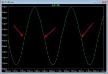
The HEC devices (Q109/110) subtract the actual output waveform
from the gate drive info outputted by the drivers.
This results in a slightly distorted "correction" waveform (see below).
The "bulges" (red arrows) is HEC compensating for gate C and device
nonlinearity.
Eliminating the HEC circuit , this OPS does .5% , maximizing the
bulges (fine tuning)can get me .007% full power 20K.
The Vfet really sucks at the X-over point. 4.1123V is "off" .... 4.1130V is
full "on" . A standard EF2/3 is too "dumb" and lacks the control to
make this transition smoothly.
The HEC "pulls the rubber band tighter" at the driver stage. A real fast
driver pair (like the toshiba 2S/A pair) would work better here.
OS
Attachments
So the SlewMOSmonster I built using 5 pair IRFP240/9240 should be capable of 400W/8R?
At least ... you could even bias it into class A , heat the room with it. 😀
OS
On my chat or PM, please, if some find this useful and would like to participate.
Just one quick comment here in case it helps others.
The models you have used for the OPS FETs are useless for distortion prediction.
Probably why you have numbers that Damir and I found too good to be true.
Best wishes
David
Run with the Cordell models, much more accurate but still not ideal.
As predicted distortion is 10 times worse.
At 1 V input 20 kHz it is .011 %.
Damir is correct.
Last edited:
No, Dave. Words don't help, please provide datas: IE measurements of real builds VS their sims with the two models for we can figure out witch one is closer.Just one quick comment here in case it helps others.
The models you have used for the OPS FETs are useless for distortion prediction.
That i know is the models i used, (don't remember who provided them) gave-me very close results to the original VSSA build measurements, and this was just a matter to compare DVSSA expected improvement with the original in the same environment.
And, anyway, who really care about 10ppm evils?
Is your tweeter able to move with the 5th harmonic of a 10KHz signal, and your ears even able to hear it at 100 times their levels ?
Nobody, neither you, went on my chat, to solve this so calling model 'mistake', I had no answer from my PM to dadod.
EOT. for me. You can understand i could consider-this now as pure bashing or lose of time ?
Anyway, as Andrej, lurking at this thread, I don't understand its purpose, the way it turns.
Comparing simulations of hundred of schematics to get the most impressive virtual numbers, without real builds, comparative real measurements and listening comparisons with serious listening reports ?
Only one member had build some of them, with this real strange conclusion: "They all sound the same."
If it is true, what the f... ? Just build the simplest and less expensive one. Every added device is a risk to lose details, and the rule "Simple is beautiful" is my verified law.
Are-we just designing amplifiers to achieve beautiful screen shots, or to listen to real music on real speakers ?
Last edited:
Is it just the models ??
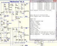
Below are the best voltage stage models ...
(Cordell's fairchild 1381/3503's)
And OUTPUT devices swapped into the circuit (#2).
WHAT ?? only 2 ppm difference @ 20K.
The amp was able to compensate for >Cob from 6pF to 500pF (the op's).
Is it the models , or the design ?
Which leads to this statement ...
This means "good" things are happening within the design. One's that
operate like this are usually tolerant of wide variations in the semi's ,
compensations , and electrical conditions.
BTW , Thimios/Bimo prototyped these ... 100+ slewmaster amps are
out in the "wild". Read deeper !
PS - generic LT and old spice models will give inferior results - Cordell/Andy C. models are precise.
OS
Below are the best voltage stage models ...
(Cordell's fairchild 1381/3503's)
And OUTPUT devices swapped into the circuit (#2).
WHAT ?? only 2 ppm difference @ 20K.
The amp was able to compensate for >Cob from 6pF to 500pF (the op's).
Is it the models , or the design ?
Which leads to this statement ...
And, anyway, who really care about 10ppm evils?
This means "good" things are happening within the design. One's that
operate like this are usually tolerant of wide variations in the semi's ,
compensations , and electrical conditions.
BTW , Thimios/Bimo prototyped these ... 100+ slewmaster amps are
out in the "wild". Read deeper !
PS - generic LT and old spice models will give inferior results - Cordell/Andy C. models are precise.
OS
Attachments

Esperado, I went to the chat page but all I get is a blank page.
As for my models, I've attached my latest collection. Open it in Notepad to understand it. This is just for BJTs. I haven't looked into other types of transistors.
Thanks, do you have any (good) V/Lfet models ? 20n20/20p20 Lfet models I just
used did not match the datasheets for Vgs params. 🙁
OS
- Home
- Amplifiers
- Solid State
- Slewmaster - CFA vs. VFA "Rumble"