Arduinos are lots of fun. It's amazing what you can do with them once you figure out coding. They are known to lock up though. That's my only concern with using them for a protection device. Looks like Valery's design still uses analogue speaker protection as a failsafe.
Is it important that the rail feeds and speaker output are at that end of the board? I saw another thread where they are talking about sawing the boards down to select the number of output devices. The boards looked very similar to these. It looked like if the power feeds were moved to between the drivers and output devices they could just saw the board off at the number of desired output devices and not need to splice the boards together again.
Ah yes, are you making reference to destroyer X's latest installment - the DxS? I'm following that one quietly to see how it progresses. I was giving some thought to the concept of a universal board along those lines.
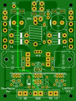
As for connector positioning, I think the idea here was to keep the high current areas well away from low current / higher impedance areas.
As for connector positioning, I think the idea here was to keep the high current areas well away from low current / higher impedance areas.
That's the thread. I was wondering if moving the rail feeds might actually help with voltage drop to the earlier stages of the amp? No power hog outputs in the path.
With the boards I've done there's sooo much copper there you could run two toasters on those rails without excessive voltage loss (the calculation said something like ~38A for a 20C rise over ambient). The voltage losses are actually designed in with the RC filters in each rail and the capacitance multipliers feeding the rest of the amplifier. Moving the connectors isn't going to save us much if any voltage headroom. It's the price we pay for catching a fair bit ripple and noise before feeding power to the more sensitive parts of the circuitry.
In-board output MOSFETs to minimize footprint...
I like that a lot. I would buy those. This actually turned out to be a nice little unit and your have made it really attractive with the help of Ranchu.
Are going to add them to your group buy? If not, I would like the gerbers.
Blessings, Terry
Last edited:
This audio circuit board design is a lot tougher than the automotive world I normally deal with. I just need to get power or signal from a to b and design the circuit to be noise tolerant. Electrical environment is terrible in a vehicle. One thing that still keeps striking me as wrong with audio boards is fusing on the amplifier instead of the supply. I realize the wiring isn't moving as much but wouldn't it make sense to protect it with the fuse as well?
Lots of different and sometimes conflicting requirements in audio. That's why you sometimes see odd looking implementations; they are usually done to accommodate certain design criteria without compromising other areas of the design. Fun ain't it?
The PSU is of course always fused protected as well. It just comes down to whether or not you want to put all the fuses on the PSU. I have a personal preference for putting all fuses on the PSU but I bent to the popular design practise here of putting rail fuses on the amplifier board.
The PSU of course ALWAYS has a fuse on the mains, and that can actually be the only fuse on the PSU if it is 'close rated' so an extended overload or short causes it to fail before any other components fail. This usually requires reliable soft starting circuitry.
Sometimes you see fuses on the transformer secondary windings but I don't think they are much good in that location. They have to be large slow blow types to survive for any length of time and therefore aren't likely to blow open when you need them to.
You also commonly see fuses in the PSU output connections. These are more useful but if I want to run two channels off one PSU I either need two sets of fuses on the PSU and none on the amplifier boards, or one set on the PSU with a fuse rating large enough to run both channels and a set on each amplifier of smaller values consummate with the expected current to be supplied. The hybrid fusing model is what I use if there are fuse on the amplifier boards, otherwise I put all fuses on the PSU.
I like that a lot. I would buy those. This actually turned out to be a nice little unit and your have made it really attractive with the help of Ranchu.
Are going to add them to your group buy? If not, I would like the gerbers.
Blessings, Terry
There has been a little interest already, so I just might order some when Spooky is ready to order.
Great work Jason. Put me down for pair these outputs and a pair of Spooky boards also.
Thanks. Good call on in-boarding the output devices. Keep an eye on the Group Buy thread for availability of boards as they become available and post interest there. I'll make sure you are on the list when these are available.
Arduinos are lots of fun. It's amazing what you can do with them once you figure out coding. They are known to lock up though. That's my only concern with using them for a protection device. Looks like Valery's design still uses analogue speaker protection as a failsafe.
Greetings from cloudy Amsterdam 😛
Jeff, you're right - though I never had it locked-up during a long time, as a pro skydiver, I know well, that in critical areas it is good to have a "reserve" 😉
So in case DC offset sensor fires, the board immediately disconnects the speakers via analogue circuit, and then follows up with the digital one.
I also use interrupts to increase accuracy in case of short-time signals accelerate response for DC offset and current overload alarms.
Terry - you will like this approach. The fact that you can adjust the delay, add functionality or improve the algorithm simply writing a couple of strings makes it very addictive 😀 During my whole career I used to deal with circuits on the edge of analogue and digital worlds, involving some low level programming. And I think it's a great combination 🙄
Cheers,
Vaery
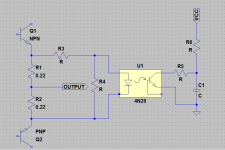
Imagine short to GND at output, so momentary Vce will be 77V. And look at SOAR region for 2SC5200 for (DC) allowed current. But for full output in normal load you need much more... It is not good idea..I want to use this simple current limiter, because I don't want add THD to may amp. If I use 2SC5200, how much current it should limit? I will use +-77V DC power supply.
In-board output MOSFETs to minimize footprint...
Jason, this one is excellent! Very refined cutie, great addition to Slewmaster collection

Imagine short to GND at output, so momentary Vce will be 77V. And look at SOAR region for 2SC5200 for (DC) allowed current. But for full output in normal load you need much more... It is not good idea..
For short circuit it will blown the fuse. I have accidentally short my amp. The transistors survived.
For PA use I agree to use SOA protection.
- Home
- Amplifiers
- Solid State
- Slewmaster - CFA vs. VFA "Rumble"