For short circuit it will blown the fuse. I have accidentally short my amp. The transistors survived.
For PA use I agree to use SOA protection.
Hi Bimo , fuses are cheap, try to buy 10 sets of fuses, the short the output of the amp, and wait for the fuses to blow 10 times then see if outputs hold. If they last, I guess short circuit protection isn't needed for you.
Regards
Hi Bimo , fuses are cheap, try to buy 10 sets of fuses, the short the output of the amp, and wait for the fuses to blow 10 times then see if outputs hold. If they last, I guess short circuit protection isn't needed for you.
Regards
Oh, yes I did. May be I have blown more than 10 fuses before I know something wrong to the connecting of my amp (shorted). You can try your self if you brave enough or stupid like me 😛
The output of my amp connect to speaker protection, when the relay is OFF, the speaker is short to ground. I connect the output of my amp to the output of speaker protection and speaker to the input of speaker protection.
If the fuse is right it can protect the amp. Is it the function of the fuse isn't it? But no one try to test it if they work or not 🙄 It surprise me 😀
Last edited:
In-board output MOSFETs to minimize footprint...
Very nice...thinking about this as OPS to Class A headphone amp.
In-board output MOSFETs to minimize footprint...
Is it fissible to design a one pair 2SC5200-2SA1943 EF TYPE II output stage layout like the one in post #4212 (one pair lateral mosfet OPS-SlewMaster Mini) ?
Is it fissible to design a one pair 2SC5200-2SA1943 EF TYPE II output stage layout like the one in post #4212 (one pair lateral mosfet OPS-SlewMaster Mini) ?
I've deviated plenty far enough with the simple lateral MOSFET design. I don't feel I should take the thread any further off course. The SlewMaster is supposed to be a Locanti-T style EF3, for which we already have designs for. I had to strip off quite a bit to get an OPS down to that size and I don't think it would honour ostripper's work to do a single pair EF2 in BJTs, though I'm sure it could be done.
Just buy the laterals and build as is. It's a thing of beauty.😀 Less parts than with BJTs and no thermal issues. Put the CFA-XH in front of it and you have a VSSA on steroids.
Terry,
I wonder what a slewmaster with 5 pairs of laterals would be like myself. Anybody know how many class A watts output 5 pairs of these lateral mosfet's would produce safely and sanely?
t
Terry, om the single pair lateral boards would the input section of a CFA-XH fit over the top of it? In other words can you use some spacers and stack both boards? t
Last edited:
Terry,
I wonder what a slewmaster with 5 pairs of laterals would be like myself. Anybody know how many class A watts output 5 pairs of these lateral mosfet's would produce safely and sanely?
t
Terry, om the single pair lateral boards would the input section of a CFA-XH fit over the top of it? In other words can you use some spacers and stack both boards? t
If I may answer...
The CFA-XH is a half inch shorter in its current form, so not quite stackable. I will likely update the CFA-XH to bring the form factor in-line with the other IPS to allow one set of stand-offs / spacers to mount them all. They, and any other IPS would then fit directly over top of the Mini OPS.
As for a 5P lateral OPS I personally have no intention of doing that. It would be a significant change in the layout since the pinout of laterals is different from BJTs and vertical MOSFETs. I only cooked up the 1P since Terry was interested in a smaller and simpler OPS (I believe) to allow testing without the need for a big heat sink. Throwing verticals in the mix was an experiment with a reasonably happy outcome and easy conversion of existing layouts.
I think I've diverted the thread enough with my tangents. It isn't with the OP's original intent. Assuming ostripper comes back 😕, I thought he would have managed to check in by now.
I have a Perreaux 9000B that has 5 pair of laterals. It is a beast. +-114V rails. I don't use it because I fear for my speakers.
The baby board is actually the same size as Jason's other IPS, Symasui, Wolverind and I think he has a Spooky coming. The other issue is the vertical heatsink required for the OPS. The IPS doesn't need to be on the main heatsink.
The baby board is actually the same size as Jason's other IPS, Symasui, Wolverind and I think he has a Spooky coming. The other issue is the vertical heatsink required for the OPS. The IPS doesn't need to be on the main heatsink.
Attachments
As usual Jason types faster than me. 😀
My initial idea was to do something even simpler. You can see my idea here. Jason helped me get it working better and then was kind enough to alter his Slewmaster OPS boards to give me something to play with. It actually works really well but it is a diversion from the "Slew rate monster" that this thread started out looking for. I was attracted to this design because I want to learn about all of this stuff and I love to build. Perfect!
If I were looking to build a multi-channel amp in one box, this little lateral would be very inviting.
Blessings, Terry
Terry,
I wonder what a slewmaster with 5 pairs of laterals would be like myself. Anybody know how many class A watts output 5 pairs of these lateral mosfet's would produce safely and sanely?
t
Terry, om the single pair lateral boards would the input section of a CFA-XH fit over the top of it? In other words can you use some spacers and stack both boards? t
I would be interested on something like that.
Also long time planning to build something with Toshibas 2SJ201 & 2SK1530 MOSFET.
Greets.
Hi Guys,
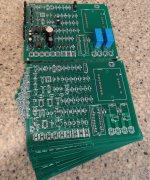
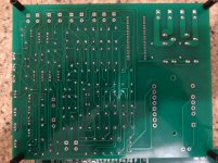
I got my Valery Protection circuit boards today. I didn't quite have all the parts yet but installed what I had. Still looking for a supplier of the Chinese plugs. If someone knows of a supplier for the transformer that fits this that would be a good thing.
I have some extra boards for those interested. PM me.
Blessings, Terry
Attachments
Cool! As soon as you get Arduino module - let me know, I will give a couple of guidelines on how to program it properly. You will also need a standard USB-to-miniUSB cable for programming.
Cheers,
Valery
Cheers,
Valery
I should get the arduino tomorrow then I just need a transformer and the miles plugs. There are some transistors in the Bom that are not on the board. Is there another part to this?
Thanks, Terry
Thanks, Terry
I should get the arduino tomorrow then I just need a transformer and the miles plugs. There are some transistors in the Bom that are not on the board. Is there another part to this?
Thanks, Terry
I think, you mention those MJE340s' that are used as temperature sensors, right? They are expected to be placed on the main heatsinks.
Hi Valery,
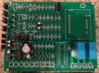
Do you have a diagram on how all this stuff hooks up? There are a lot of plugs on this board. I'm assuming that the MJE340s must use a couple of the plugs but they are only two pin plugs so obviously there is some modification needed. I see +/-52V ?
I received my nano today. Some pins have different designations. Can you take a look and see if there is any problem?
Thanks, Terry
Attachments

Terry,
It looks to me that the PCB is laid out expecting a 2 x 16 MCU. The one you have is 2 x 15. However the pins that are present on your MCU appear to be in the same sequence as the one described on the PCB. Unless something is mapped to those missing pins I would think your MCU should work!
It looks to me that the PCB is laid out expecting a 2 x 16 MCU. The one you have is 2 x 15. However the pins that are present on your MCU appear to be in the same sequence as the one described on the PCB. Unless something is mapped to those missing pins I would think your MCU should work!
Hi Terry,
Carl is right, just leave 2 holes on the left (marked SPK and HV12) unused - they are reserved for those clones having 2x16 pinout. I actually use an IC panel, so that I can plug Arduino in and out, but it can be soldered-in as well.
So, for programming, you need to install the software, as described in my document, copy the firmware to Arduino directory, connect Arduino via a miniUSB cable. See the new com port appearing after you connect Arduino - select this new com port in the software (Tools - Serial Port - COM-something-not-1-normally).
Open the firmware listing (File - Sketchbook - PowerAmp_05_int_tube).
Make sure the delays are set correctly - I use a rather "conservative" setup now:
const int TubesAreHere = 1; // 1 = Tubes, 0 = NO Tubes
long heatingDelay = 30000; // wait for tubes pre-heating (mS)
long inrushDelay = 10000; // wait for soft start (mS)
long speakersDelay = 20000; // wait before connecting speakers (mS)
Now, make sure 2 lines are un-commented, roughly in the middle of the listing:
checkDCoffsetAlarm();
checkOverloadAlarm();
// !!!! Uncomment in production version !!!!!!!!!!!!!!!!!!
checkACFailureAlarm();
checkOverheatAlarm();
// ************ Continue with cases if any *************
If the lines below "!!!! Uncomment..." warning are commented - remove those slashes in the beginning of each line. Sorry, I most likely forgot to do this after I tested the firmware with my special test board. Now you can upload the software (see the LEDS flickering on Arduino) and that's it - it's ready to control the board.
Those MJE340 sensors use only 2 wires for connection - their C-B are connected. So, one wire is C-B, the other is E. The one, which is C-B, goes to the pin that is closer to the PCB edge (Thermo1, Thermo2). You can run initial testing without them, also without Bias-left and Bias-right connections.
+/-52V are actually your OPS rails. They can be +/-70V, no problem - tested in my setup. It is just marked "historically" from the very first amp I used this board for.
Cheers,
Valery
BTW, you can use the LEDs with 1K resistors in series instead of the big relays for initial testing, just to see everything goes right - it's easy to see them switching on one by one as soft-start is performed...
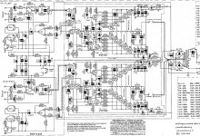
Also, for better understanding of the plugs' polarity on the board. You can see a sort of a "key" on one side of each 2-pin plug. This plug always indicates the "bottom" pin, as shown on schematic. The other pin is the "top" one.
Also, for better understanding of the plugs' polarity on the board. You can see a sort of a "key" on one side of each 2-pin plug. This plug always indicates the "bottom" pin, as shown on schematic. The other pin is the "top" one.
Last edited:
- Home
- Amplifiers
- Solid State
- Slewmaster - CFA vs. VFA "Rumble"