Hi Jason.
I just checked and it goes from +-44v at idle to +-40.5 when driven hard into 4 ohms. I stood the heatsink on end and it has been playing pretty loudly into 4 ohms for about a half hour and It is pretty warm but I can keep my hand on it indefinitely so probably OK. If I were building it into a case I would give each OPS its own heatsink. BTW, it didn't get near this warm into 8 ohm. I actually think this would be worth making gerbers for. At this size the boards would be cheap and being modular make planning a case easier. I cringe when I keep seeing the really long PCB's. Take a long and often tall heatsink to accommodate them. This little unit is pretty slick and doesn't take many parts. Only issue now is that some of the IPS units we are building need some values changed to deal with the lower rails. My CFA and Symasui were ok but the Spooky didn't light the LEDs. Probably just a matter of changing the resistors feeding them. So far, I like it. I'll make the changes tomorrow to see if the base stopper change can get rid of the extra caps.
Blessings, Terry
I would twist the wires going between the frontend and OPS boards. This reduces the loop inductance and keeps them from coupling to other fields, and would make them less likely to cause strange RF effects that occur randomly with workbench changes.
Will do.
Hi Jason.
I actually think this would be worth making gerbers for. At this size the boards would be cheap and being modular make planning a case easier.
Blessings, Terry
Gerbers are easy enough. Let's debug and settle on design values so I can make accurate schematic changes and make sure the board is good to go before putting something out there that someone might make a significant investment in.
I have to thank you for doing the heavy lifting here by doing a physical build and working on debugging it. Hats off to you.
Yes, of course. I'll try to find time tomorrow to try out the changes you selected. Christophe is telling me that 150mA is the sweet spot for these MOSFETs, so I want to at least try them there. I'll probably have to put a fan on the heatsink. 😉
How to build a 21-st century protection board 😉
Hello All,
I have promised (at least to Terry 🙂) to give more details on my "smart" protection board components and build peculiarities. I have compiled this document for those who are interested in building it.
Gerbers and firmware are available on request.
Questions, suggestions are welcome.
Cheers,
Valery
Hi Terry,
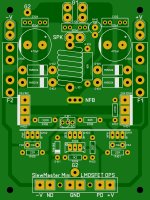
Here is the schematic, illustration of PCB layout and PCB photo of the latest version of protection module. If you like it, I can share gerbers. I will also give more details on standby transformer and relays used in the circuit, share the firmware and show how you can adjust the delays.
All indication is performed with a single LED - rather elegant, I think.
I am also working on the new hybrid front end - will give more info soon. It's got all the voltage gain performed purely by the tubes (2 x 12AU7) and rather light NFB - preserving the "tubish sound" - hopefully 😛
Cheers,
Valery
Hello All,
I have promised (at least to Terry 🙂) to give more details on my "smart" protection board components and build peculiarities. I have compiled this document for those who are interested in building it.
Gerbers and firmware are available on request.
Questions, suggestions are welcome.
Cheers,
Valery
Attachments
Gerbers and firmware would be great. My Arduino coding is painfully slow.
Is there any reason a VF-4 automotive relay can't be used for these type of protection circuits? They're cheap and readily available everywhere. I think there would be less worry of contacts welding as they are designed to switch high current DC.
Is there any reason a VF-4 automotive relay can't be used for these type of protection circuits? They're cheap and readily available everywhere. I think there would be less worry of contacts welding as they are designed to switch high current DC.
Scratch that VF-4 question. I see the contact voltage rating has dropped as fast as the prices. They used to be good for 85 volts.
Scratch that VF-4 question. I see the contact voltage rating has dropped as fast as the prices. They used to be good for 85 volts.
Right, I actually chose the ones suitable for mains. It's 220VAC here, well, for 110VAC they will be fine anyway. Although, the choice is yours - there may be lots of options around 😉
Hi Valery,
Thanks for the docs. I should have my boards in a couple of weeks. I will have a few extra. PM me if interested.
Thanks for the docs. I should have my boards in a couple of weeks. I will have a few extra. PM me if interested.
Cool thing is I'm still learning something and hopefully others following these threads are too.
Blessings, Terry
yes, .... me too. Enjoying this greatly.
THx-RNMarsh
Hi Jason,
OK, yesterday ended up being a family day so I didn't get back to the OPS until today. I changed R107 to 470R, R108 to 330R, R106 to 68R and R104 to 2k2. I removed the 330p cap from the MOSFET.
Oscillation is gone.
16mA at drivers.
Quiescent current at the fuse starts at 105mA with trimmer all the way in and ends at 145mA with the trimmer turned all the way out. It is playing fine but it just seems like there is not enough adjustment. Seems like I should be able to get the bias a lot lower if I wanted and if I need 150mA at the device I need still more as 145mA-16ma = 129mA.
Looks like maybe still it need a little more fine tuning?
Thanks, Terry
We could move to a 1k potentiometer and make R104 1K8 (or even 1K5 if the range needs tweaked a little more). We aren't going to get a huge range od adjustment. As far as I'm concerened anything from 100mA to 150mA is good, I usually shoot for 120mA but that's just a personal choice.
Ok, so here's where it is set right now.
+-44Vdc rails at idle.
R104=1k2
R106 68R
R107=470R
R108=330R
1K trimmer.
With trimmer set to 1k, current at the fuse is 70mA I was able to adjust the current to 166mA without turning the trimmer all the way out. I will check the actual setting after it has played for a while. I see 16.2mA across R106. Looks like everything is now where it should be. I'm going to let it play for a while and then recheck the bias and heatsink temps. This sounds every bit as good as my VSSA so I'm pretty tickled with how it came out. Certainly a worthwhile option for someone who wants something smaller and simple.
I'll report back with some temp readings and any notable bias changes after it has played for while.
Blessings, Terry
Going with all just as it is except using a 2K trimmer will allow lower bias settings with the same maximum bias setting, as set by R104.
Minor housekeeping, but now looking like the attached. There is room to re-integrate the capacitance multipliers (simplified of course). Any value in that or just keep this one simple?
Minor housekeeping, but now looking like the attached. There is room to re-integrate the capacitance multipliers (simplified of course). Any value in that or just keep this one simple?
Attachments
Hi Jason,
Looks really nice. I like the idea of the 2k pot. The bias is not touchy so that sounds like a better option. After letting it play for a while I rechecked some things. The driver heatsink still feels really hot and it reads 19mA with the bias set to 166mA so I think I should either go up in value on R104 or down in the bias.
This is just my thinking, but if you could fit it, I would like to see a trace, maybe on the top, to jumper the two G2 nodes so we don't have to solder that long jumper wire.
Blessings, Terry
R104 sets the maximum allowable bias setting, did you mean R106? Next stop for that would be going up to 75 or 82 ohm, again to target the 16mA mark. Mind you they wont be exactly cool shaving off just 3mA, some dissipation of heat in the drivers is going to happen. A little more driver heatsink area maybe? You likely don't need to run with quite as much bias as you are currently using, maybe back down to 120mA-ish. I know the general opinion is that 150mA is a 'sweet spot' for the output bias but I'd suggest in proper testing folks couldn't tell if lower values of bias were being used.
A top side trace to connect the G2 points is easy enough and likely wont be any worse than a wire, so I'd be inclined to do that.
A top side trace to connect the G2 points is easy enough and likely wont be any worse than a wire, so I'd be inclined to do that.
Hi Jason,
Yes, R106. I am on my tablet and was typing from memory. I'll back the bias back down to 136mA and check R106 again. It is likely OK at that setting. I have another amp on the bench right now but I will try to get back to it today.
Yes, R106. I am on my tablet and was typing from memory. I'll back the bias back down to 136mA and check R106 again. It is likely OK at that setting. I have another amp on the bench right now but I will try to get back to it today.
Hi Valery,
Can you tell me what the pin spacing is for the Molex connectors on your boards?
Thanks, Terry
Can you tell me what the pin spacing is for the Molex connectors on your boards?
Thanks, Terry
Hi Valery,
Can you tell me what the pin spacing is for the Molex connectors on your boards?
Thanks, Terry
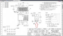
Hi Terry, pin spacing is 5.5 mm = 0.217 in. By some reason this one is metric originally...
Attached is a fragment of Molex datasheet with spacing marked.
Cheers,
Valery
Attachments
- Home
- Amplifiers
- Solid State
- Slewmaster - CFA vs. VFA "Rumble"