We need to determine whether the oscillation is local to the MOSFETs or the drivers. Look at the signal on the emitter of one of the drivers to see if the oscillation is present there or not. If it is the MOSFET oscillating locally try increasing the base stopper value, maybe to 470R to see if we are on the right track or not.
Just playing with the Lateral MOSFET OPS in simulation suggests it should be quite stable. Changing things up and down like base / gate stoppers or the driver compensation capacitance doesn't change much. No weirdness in gain or phase.
Have you tried a different IPS known to work well just to eliminate it as a source of issues?
Have you tried a different IPS known to work well just to eliminate it as a source of issues?
Hi Jason,
Yes I tried Symasui, Spooky and CFA-XH BV. The oscillation happens on the way up. From about 3.5vac to about 10vac. Then it goes away and the sine wave is clean. Maybe a hint, it is worse with the DMM attached to the output? One channel is a little worse than the other but they both do it. There is a hint of the oscillation on the driver emitters but not every time I cycle the sine wave. It is there on the output every time. With the DMM removed it is much less. Aside from the oscillation, both sine waves and square wave look very nice.
Another thing I noticed is that it is very sensitive to having other ground sources attached to it, i.e. the scope. presently there is no earth ground to anything. That is usually not a problem but I will see if adding that will have an effect on the oscillation. On other amp where I had oscillation, the grounding sensitivity went away once we found the source of the oscillation.
Blessings, Terry
Hi Jason,
Yes I tried Symasui, Spooky and CFA-XH BV. The oscillation happens on the way up. From about 3.5vac to about 10vac. Then it goes away and the sine wave is clean. Maybe a hint, it is worse with the DMM attached to the output? One channel is a little worse than the other but they both do it. There is a hint of the oscillation on the driver emitters but not every time I cycle the sine wave. It is there on the output every time. With the DMM removed it is much less. Aside from the oscillation, both sine waves and square wave look very nice.
Another thing I noticed is that it is very sensitive to having other ground sources attached to it, i.e. the scope. presently there is no earth ground to anything. That is usually not a problem but I will see if adding that will have an effect on the oscillation. On other amp where I had oscillation, the grounding sensitivity went away once we found the source of the oscillation.
Blessings, Terry
Hi Terry,
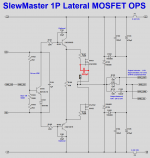
P-channel laterals (2SJ162 in your case ~ 900pF) have got significantly higher input capacitance, than N-channel ones (2SK1058 ~ 600pF), resulting in rather unbalanced OPS at high frequencies.
Try adding a 330pF cap between the gate and the source of 2SK1058 as shown on the picture - this will make the whole thing much more balanced and stable.
Also, slight increased stoppers may help (I would use 470 ohm for R107, R108), however the cap is more important.
Cheers,
Valery
Attachments
Hi Valery,
That was it. Straightened it right out. I have it playing with the original BV modded CFA-XH IPS. Wonderful. I have it hooked up to the A/B setup along side my PMA VSSA (it uses the exact same outputs). Too close to call. Great sound stage as you would expect. This one has slightly more output but it is running on +-45V rails and the VSSA is on +-36V. Still only able to get 90mA at the fuses but that seems to be enough. The scope looks great.
Now I wonder why on the VSSA/peeceebee there is no special compensation for the 2SK1058. Both sides get the same thing. Cool thing is I'm still learning something and hopefully others following these threads are too.
Thanks again Jason for doing the layout for me. This makes for a nice compact setup for folks who are limited for space and heatsink.
Blessings, Terry
Attachments
Another way to compensate for the different capacitances of the outputs is to use different gate stopper values between the N and P channel devices. Choose the values so the time constant if the same for both.
hi Jason,
How do you calculate that? Do you have a suggestion for this application? The cap is working fine but I'd like to learn how to do the other as well.
Also, do you have suggestions for changes that may be needed for the VBE multiplier are do you think 90mA per rail is sufficient?
Thanks, Terry
How do you calculate that? Do you have a suggestion for this application? The cap is working fine but I'd like to learn how to do the other as well.
Also, do you have suggestions for changes that may be needed for the VBE multiplier are do you think 90mA per rail is sufficient?
Thanks, Terry
hi Jason,
How do you calculate that? Do you have a suggestion for this application? The cap is working fine but I'd like to learn how to do the other as well.
Also, do you have suggestions for changes that may be needed for the VBE multiplier are do you think 90mA per rail is sufficient?
Thanks, Terry
Let's say the 2SJ162 has a gate stopper of 100Ω and a gate capacitance of 900pF, the RC time constant is just RgatexCgate=RC time constant, so 100x900x10^-12=90nS. If we want 'balance' we need a resistance on the gate of the 2SK1058 that gives the same time constant. So, Rgatex600pF=90nS, solve for Rgate. In this case Rgate needs to be 150Ω.
This could be a valid experiment, remove the capacitor and increase R107 to 150Ω and see if the effect is the same. I'd even suggest since it appears sensitive to set R107 to 470Ω and R108 to 330Ω, same equalization of the time constant, just with higher values overall and see if you can get it to function stably without the added capacitor.
For the VBE, try R104 as 2K4 or even 2K2 if needed and see if you are closer to the sweet spot.
Thanks again Jason for doing the layout for me. This makes for a nice compact setup for folks who are limited for space and heatsink.
Blessings, Terry
So, if we can iron out the required component details does this represent a desirable OPS variant? Or was it just a flash in the pan?
It has been playing for a couple of hours without issue. I will try the resistor changes just to see if it will work without those extra caps. Funny, the very first schematic I posted in the other thread had 470R for the base stoppers.
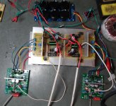
One more thing, I have the drivers on 3" X 1-1/4" heat sinks, They are running pretty hot, as in , I can hold on to them but just barely. The bias is only about 90mA. If I change R107 so I can raise the bias, won't that make the drivers run hotter yet? I have 1.068V across the 47R, (R106)
Thanks, Terry
I actually think it is kind of a cool little unit. Of course the Cap multiplier is gone for those who want that and I'm not sure about the slewrate but it sounds great. I have a cap multiplier on the VSSA I'm comparing it to and I don't hear any problems at all and I'm just using a small PSU with this. (6X4700)
One more thing, I have the drivers on 3" X 1-1/4" heat sinks, They are running pretty hot, as in , I can hold on to them but just barely. The bias is only about 90mA. If I change R107 so I can raise the bias, won't that make the drivers run hotter yet? I have 1.068V across the 47R, (R106)
Thanks, Terry
So, if we can iron out the required component details does this represent a desirable OPS variant? Or was it just a flash in the pan?
I actually think it is kind of a cool little unit. Of course the Cap multiplier is gone for those who want that and I'm not sure about the slewrate but it sounds great. I have a cap multiplier on the VSSA I'm comparing it to and I don't hear any problems at all and I'm just using a small PSU with this. (6X4700)
Last edited:
Given Terry's comparison to the VSSA it does sound like a viable small format output section. What do you estimate that a single pair of those mosfet devices can output into 8 ohms?
Great thanks still4given sharing all your experience these amps. Because jkuetemann mention "time constant/RC function" regarding 2SK1058/2SJ162 devices i have some thoughts of same but has to do your A/B setup.
1: My thoughts are take two of these great amps that you remember have some difference in their way reproduce square waves with resistive load not speakers, make pictures of their squarewaves under same conditions 100/1K/10K/20K/50K/100K Hz.
2: Now setup those two amps in your A/B setup and trim the setup to same levels and conditions as point one, still with resistive load not speaker. Now make pictures their square waves 100/1K/10K/20K/50K/100K Hz.
3: Respective amps should now show same pictures inside A/B setup as outside. It's thoughts to see if the one that has widest band will be prevented to show because A/B setup impedances RC time constants ruin it's presented input signal.
It's to see if the A/B setup makes the amps stretch their specs and not being prevented by what is presented at input. Comments welcome if wrong this will reveal something. Admit will give still4given some work, overall forget if it doesn't suit.
Terry,
Those are some really small heat sinks. I wonder what a proper size sink would be for those devices?
Those are some really small heat sinks. I wonder what a proper size sink would be for those devices?
Bump R106 to be 68R to get the EF current down to 16mA.
The gate stoppers need to be in place but it offers the best performance when they are as small as practical. In this case there will be no audible difference with them being 470R (or the 470R / 330R combination).
The gate stoppers need to be in place but it offers the best performance when they are as small as practical. In this case there will be no audible difference with them being 470R (or the 470R / 330R combination).
Given Terry's comparison to the VSSA it does sound like a viable small format output section. What do you estimate that a single pair of those mosfet devices can output into 8 ohms?
Run it on 45-50V rails and it should give about 100W average output maximum.
Hi Guys,
Cool, I have some work to do. 😀
Brytt,
Those are some good recommendations. I will try those things in the coming days. I would like to see just what influence my test setup has on the square waves. Has to have some affect. There are a lot of extra cords, connections, pots, switches etc that wouldn't be there in an optimized system. My feelings have always been that since both amps are subjected to the same restraints that it is fair but it will be good to see just how much they are being limited. I'll definitely get to this this coming week some time.
Jason,
I will make those changes and see how it goes.
Kind,
Yeah, that heatsink is probably a little small but it is hanging in there driving 4ohms. I just happened to be available so I used it. I will have to see how it does when I get the bias up where it should be. It's pretty warm right now but I have it laying down. I'm going to go stand it on it's side and see how it does.
Blessings, Terry
EDIT; We were typing at the same time. I measured it into an 8ohm resistor and it clips at 27vac. My transformer is a little small so it sags down to about +-42V at full output so I'm getting about 91W with that. I can hook up a bigger transformer and retest. I'm not sure if it is safe to run it at +-47V into 4 ohms though.
Cool, I have some work to do. 😀
Brytt,
Those are some good recommendations. I will try those things in the coming days. I would like to see just what influence my test setup has on the square waves. Has to have some affect. There are a lot of extra cords, connections, pots, switches etc that wouldn't be there in an optimized system. My feelings have always been that since both amps are subjected to the same restraints that it is fair but it will be good to see just how much they are being limited. I'll definitely get to this this coming week some time.
Jason,
I will make those changes and see how it goes.
Kind,
Yeah, that heatsink is probably a little small but it is hanging in there driving 4ohms. I just happened to be available so I used it. I will have to see how it does when I get the bias up where it should be. It's pretty warm right now but I have it laying down. I'm going to go stand it on it's side and see how it does.
Blessings, Terry
Run it on 45-50V rails and it should give about 100W average output maximum.
EDIT; We were typing at the same time. I measured it into an 8ohm resistor and it clips at 27vac. My transformer is a little small so it sags down to about +-42V at full output so I'm getting about 91W with that. I can hook up a bigger transformer and retest. I'm not sure if it is safe to run it at +-47V into 4 ohms though.
Last edited:
Your'e great, take your time......Cool, I have some work to do. 😀.....
No, into 4 ohm I'd be satisfied with a slightly lower supply voltage. A somewhat soft PSU is actually good in this application. It will deliver the short transients but sag to a safer level under a consistent demand from a more difficult load.
- Home
- Amplifiers
- Solid State
- Slewmaster - CFA vs. VFA "Rumble"