Hi Bimo, yes, quiescent current will stabilize, assuming that in a normally operating circuit those drivers heat-up in a similar way, so you can track any single one of them.
Output transistors - it is important that the wires, connecting their collectors and emitters to PSU and output sockets are as "fat" and as short as possible. The base wires, obviously going to PCB, may be thinner and longer, however I would consider 25cm (~ 10 inches) as a practical maximum...
Cheers,
Valery
Thank you, Valery.
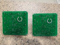
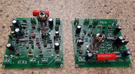
Well I am now enjoying my 4 channel class A CFA-XH BV2 with 2 pair output stage with fully regulated input stage.
This powers the mids and tweeters of my mains and they definitely sound very nice and different from the simple blameless complementary feedback that I had before that were also biased into class A. The treble sounds great, very smooth and relaxing, they don't put a foot wrong and sound refined and detailed to a point.
The case is lit up like a Christmas tree of course with all the LEDs. which I rather like.
This powers the mids and tweeters of my mains and they definitely sound very nice and different from the simple blameless complementary feedback that I had before that were also biased into class A. The treble sounds great, very smooth and relaxing, they don't put a foot wrong and sound refined and detailed to a point.
The case is lit up like a Christmas tree of course with all the LEDs.
which I rather like.Hi 5th, did you match the transistors on your CFA-XH and if so what method did you use?
Cheers
Cheers
I didn't match anything except I used these for the input stage which should be inherently well matched.
http://www.nxp.com/documents/data_sheet/BC846BPN.pdf
I think with the ability to trim the constant current sources of the input stage and the ability to adjust the DC offset with BVs input mod, if you can measure the THD you can pretty much compensate for a bit of transistor mismatch. Otherwise I think you want to hFE/beta match the input pair. I have a multimeter which will do this, but if the transistors are any good from the manufacturer then you might have a problem doing this. I say this because most hFE bins are quite large, ie the NPNs in a certain bin might be 300-500. And the PNP might also be 300-500. Trouble is if they are from the same batch you're likely to get all your NPNs at say 340-350, then all the PNPs could be at 440-450. So even if you buy 100 of each, you're not guaranteed that any of them will match.
Usually people match all NPNs and then all PNPs, not match PNPs to NPNs. I mean output stages only care that all the NPNs have the same hFE, the same with the PNPs, not that the NPNs and PNPs are both equal. The same is true for the input stages. LTPs have transistors of the same type, the same is also true for current mirrors, so matches are easy there. Matching an NPN to a PNP is considerably harder.
I've never had any luck matching PNP to NPN for exactly the reasons you state. Generally I buy small signal transistors in bulk on cut tape and parts on the same piece of tape are tightly grouped but the compliments are way off. This is the main reason why I've favoured symmetrical designs to date and favoured single ended topologies instead.
Hi Christian,
I'm looking forward to it too. It will depend on whether or not the little transformer gets here before I leave on vacation. If not, you may be done with yours before I get back. 😉
I'm looking forward to it too. It will depend on whether or not the little transformer gets here before I leave on vacation. If not, you may be done with yours before I get back. 😉
You can try this:
- Plug your cable in the inputs.
- Remove C12.
- Tune C1 & C18 to have no oscillation and a flat bandwidth at HF (no peak in the response curve).
- Plug-in a square wave generator @ 50Khz to your cable.
- Replace C12 and tune it to have no peak in the square waves.
This will be you minimal C12 value, that you can increase for best listening results.
Hello Esperado and others,
That Did the trick! Increasing comp caps from 47p to 57p Was enough. Now the amp is Silent as graveyard and no sign of oscillation.
Thanks again!
Brief listening session have very positive impression but more about This Later.
Jarno
Hello Esperado and others,
That Did the trick! Increasing comp caps from 47p to 57p Was enough. Now the amp is Silent as graveyard and no sign of oscillation.
Thanks again!
Brief listening session have very positive impression but more about This Later.
Jarno
Interesting, your hum / buzz issue was the result of being somewhat under-compensated?
I have a project with the same symptom - all is well until an input cable is connected to another mains operated piece (an isolated source like a portable MP3 player is fine) where I get a slight line frequency noise. The rest of my gear is double insulated commercial stuff without any connections to ground.
I will have to check out adjusting my compensation values to see what happens.
Hello Esperado and others,
That Did the trick! Increasing comp caps from 47p to 57p Was enough. Now the amp is Silent as graveyard and no sign of oscillation.
Thanks again!
Brief listening session have very positive impression but more about This Later.
Jarno
Jarno can you detail how you do, for those (as me) are at the beginning. I doubt but may be you have picture from process or screen shot. I think this steps is important for every potentiel buider.
Marc
Jarno can you detail how you do, for those (as me) are at the beginning. I doubt but may be you have picture from process or screen shot. I think this steps is important for every potentiel buider.
Marc
Hi Marc,
Unfortunately I have no pictures available.
The process itself was very easy and goes as follows:
1. Solder trimmer caps parallel to the current comp caps.
2. Connect amplifier into the signal generator.
3. I put scope on the outputs of the amplifier.
4. verify that the amp behaves as predicted (in my case 50hz hum 0,5 VAC.
5. Feed the amp with 50khz square wave and monitor the scope output.
6. Increase the comp cap value carefully on both sides (my caps were 5-20p).
7. when the oscillation stops you are done.
8. measure or evaluate the total comp cap value.
In my case I would have gotten away without scope or signal generator because the hum was visible with standard multimeter also. Just create the conditions where the hum is there. Then connect ac meter in the amp outputs and start triming the caps. When my amp was compensated properly there were ac less that 2mV on the amp output. Of course If the hum is ground loop related this procedure does not help.
I hope this writeup helps.
Jarno
The problem can be something else too. Like ground loops, or ground currents between your two gears.I have a project with the same symptom - all is well until an input cable is connected to another mains operated piece (an isolated source like a portable MP3 player is fine) where I get a slight line frequency noise. The rest of my gear is double insulated commercial stuff without any connections to ground.
The first thing to do is to measure the voltage between the plug ground (un connected to the amp) and the gound of the RCA input of the amp. Change the AC sens (phase and neutral) and chose the sens with the less voltage.
Note about compensation caps. Most of the time, They are set between collector and base of the VAS. I think it is not optimal, as it create a current charge at HF for the transistor. I prefer to put them between output and bases: Ouput transistors can deliver the current, and it reduce H.F.distortions.
Hi Marc,
Unfortunately I have no pictures available.
The process itself was very easy and goes as follows:
1. Solder trimmer caps parallel to the current comp caps.
2. Connect amplifier into the signal generator.
3. I put scope on the outputs of the amplifier.
4. verify that the amp behaves as predicted (in my case 50hz hum 0,5 VAC.
5. Feed the amp with 50khz square wave and monitor the scope output.
6. Increase the comp cap value carefully on both sides (my caps were 5-20p).
7. when the oscillation stops you are done.
8. measure or evaluate the total comp cap value.
In my case I would have gotten away without scope or signal generator because the hum was visible with standard multimeter also. Just create the conditions where the hum is there. Then connect ac meter in the amp outputs and start triming the caps. When my amp was compensated properly there were ac less that 2mV on the amp output. Of course If the hum is ground loop related this procedure does not help.
I hope this writeup helps.
Jarno
Thanks for the clear explanation, it fix good in a few word the beahvior.
Marc
I highly recommend you follow *exactly* the procedure i printed here: http://www.diyaudio.com/forums/solid-state/248105-slewmaster-cfa-vs-vfa-rumble-174.html#post3980893.The process itself was very easy and goes as follows:...
It will give-you the best results both for stability and IM.
Explore with your scope, *with no input filter cap*, the bandwidth of your amp and ensure there is no level increase at HF (flat response curve) trying to have max HF response, just before the hf cut-off.
If not, there is a risk your amp is under (stability) or over (distortion) compensated.
Once this is done, explore a 50KHz square wave signal and set input filtering cap minimal for no overshoot. You'll have the best compromise between slew rate and IM.
You can increase this filtering cap value, after, listening to music. Filtering harder the HF signal at input can bring-you even more transparency during transients. You'll find an optimum value, between 20KHz phase turn and overshoot. It can depend too of your speakers.
Last edited:
I highly recommend you follow *exactly* the procedure i printed.
It will give-you the best results both for stability and IM.
Explore with your scope, *with no input filter cap*, the bandwidth of your amp and ensure there is no level increase at HF (flat response curve) trying to have max HF response, just before the hf cut-off.
If not, there is a risk your amp is under (stability) or over (distortion) compensated.
Once this is done, explore a 50KHz square wave signal and set input filtering cap minimal for no overshoot. You'll have the best compromise between slew rate and IM.
You can increase this filtering cap value, after, listening to music. Filtering harder the HF signal at input can bring-you even more transparency during transients. You'll find an optimum value, between 20KHz phase turn and overshoot. It can depend too of your speakers.
As i perfectly understand the steps with 50 square, and the impotance of removing filter caps, the bandwith exploring is a little confuse to me (i understand the whole princip but the how to is less clear)
Marc
1- Ensure your generator is linear up to 10MHz at the input of your amp...As i perfectly understand the steps with 50 square, and the impotance of removing filter caps, the bandwith exploring is a little confuse to me (i understand the whole princip but the how to is less clear)
2- Look at the level at the output of amp, sweeping HF. You will probably find
a peak in the response curve, just before the level begin to decrease.
Like in the 147 Ohm curve of the following image.
Increase the value of your Miller cap (or such) untill this bump just disappears. Like in the 300 Ohm curve of this image.
Done.
An externally hosted image should be here but it was not working when we last tested it.
Dont take care of the scale of this image, your amp will cut off before 10MHz.
Last edited:
Thanks for explanation, i must yet search how exact achieve band exploration with scope as the scope give level for one frequency when connected to GF.
Marc
Marc
No need to even synchronise your scope. Just look at the peak level on it, while sweeping the generator.Thanks for explanation, i must yet search how exact achieve band exploration with scope as the scope give level for one frequency when connected to GF.
Oh, of course, do-it at low level, if you don't want to burn the resistance of your Zobel ;-)
Last edited:
No need to even synchronise your scope. Just look at the peak level on it, while sweeping the generator.
Oh, of course, do-it at low level, if you don't want to burn the resistance of your Zobel ;-)
Thanks for advise. The low level precaution was already integrated but good to reminded.
Marc
- Home
- Amplifiers
- Solid State
- Slewmaster - CFA vs. VFA "Rumble"