Ok. Well 1% is -40dB. Distortion of CD players is normally quoted at less than 0.01%. So is 1% of peak signal output a realistic worst-case ultrasonic noise level?
Actually, the opposite is true. All signals at all times have a slew rate, which is zero for DC. Slew rate is just another name for slope or tangent or first derivative.
Amps have a slew rate limit. People sometimes confuse slew rate limit with slew rate, because they lazily call slew rate limit the 'slew rate'.
I have to confess that i did it too.... 🙂
I really thought that the term "slew" and "slewing" got in this special field a special meaning i.e. that "slewing" used in the context with amplifiers means an amplifier is working at its maximum rate of change.
But i could not find an according entry in a dictionary, although for the last 40-50 years afair every data sheet only mentioned "slew rate" (and not slew rate limit); used also in german datasheets as the socalled "Anstiegsgeschwindigkeit" .
Of course, enough to check any datasheet of any opamp. Slew rate always means the maximum dv/dt the part is able to make (when driven with perfect step, i.e. with Tr--> 0).
Last edited:
..... and distortion rises well before the SR limit is reached. Which is why a very good margin ought to used in the amp... to assure lowest possible dynamic distortion.
THx-RNMarsh
THx-RNMarsh
Not that simple.
This is what I thought about op amps until I looked at this closely.
Spice simulation on an LT6090 shows a 30V/uS which fits quite well with the datasheet figure.
However the dV/dt, LT6090 is able to cleanly achieve is only 4.5V/uS. Beyond this limit, the THD becomes very bad.
The datasheet figure is not relevant to audio, which is obvious, it is a characteristic of large signal NON linear behavior.
The real figure, relevant for quality audio is much lower.
IMHO, datasheet slew rate is totally misleading in audio applications, as well as slew rate claims with no clear definition.
some audio op amp datasheets use the slew rate that gives 1% THD with a sine wave
1% THD is almost at slewing limit.
This has been reported by many...... and distortion rises well before the SR limit is reached. Which is why a very good margin ought to used in the amp... to assure lowest possible dynamic distortion.
THx-RNMarsh
I think it is where the recommendation of targeting a slew rate limit for any amplifier that is 5times to 10times that slew rate that would be required to pass the fastest signal (combination of amplitude and frequency) in the required passband.
eg of fastest signal
Power Amplifier passing 10kHz at maximum level, or 15kHz @ -3dB, or 20kHz @ -8dB, or interference spike @ 100kHz @ -20dB, or any other that seems plausible.
Choose that with the highest slew.
However the dV/dt, LT6090 is able to cleanly achieve is only 4.5V/uS. Beyond this limit, the THD becomes very bad.
I agree that distortion rises well before reaching the slew rate limit.
But your 4.5V/us is still more than 20 times what is required for a max opamp output of 10VRMS at 20kHz. So in a practical application this limit is irrelevant.
Jan
This behavior used to be called Slew Induced Distortion, if I remember correctly...... and distortion rises well before the SR limit is reached.
Analysing its origin and investigating the ways to combat it would be more fruitful than speculating about the maximal slew-rate performances of circuits which, in most cases, seem to be amply sufficient.
Last edited:
This behavior used to be called Slew Induced Distortion, if I remember correctly.
Yes, can be find here:
http://www.waltjung.org/PDFs/Walt's_Blog_2014_Classic_Articles_Page.pdf
See article overview attached.
I still maintain we are re-inventing stuff ;-)
Jan
Attachments
Here's a question. Why do some amplifier designs boast bandwidths of 100KHz, 200kHz or more given that keeping ultrasonics out of the amp is a good thing for avoiding slew induced distortion? Why don't they use an input filter to bring the bandwidth right down?
Here's a question. Why do some amplifier designs boast bandwidths of 100KHz, 200kHz or more given that keeping ultrasonics out of the amp is a good thing for avoiding slew induced distortion? Why don't they use an input filter to bring the bandwidth right down?
Easy. You get about 0.2 degree phase shift at 20kHz which will, as anybody knows, cause massive time smearing. Which sounds, also as anybody knows, horrible!
Jan
source, input bandwidth limiting should be independent of PA feedback gain intercept
its quite reasonable for audio power amp global feedback gain intercepts to be over 1 MHz today with fast output Q
and there's no reason to let 1 MHz crap into the amp input
in fact the input filter could be 18 kHz if you believe in kgrlee, Richard Lee's tests, lit review that limited bandwidth is actually preferred by skilled listeners
Here's a question. Why do some amplifier designs boast bandwidths of 100KHz, 200kHz or more given that keeping ultrasonics out of the amp is a good thing for avoiding slew induced distortion? Why don't they use an input filter to bring the bandwidth right down?
Last edited:
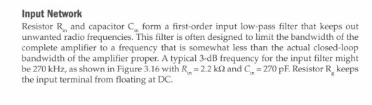
Here's a snippet from Bob Cordell's power amplifier book.
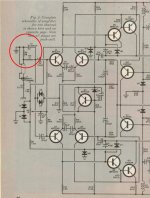
Also attached is the schematic of James Bongiorno's 200W/8R "Ampzilla" from Popular Electronics magazine, September 1974. I've circled the input filter (R3, C1) in red. Don't forget to add (2 x ~60 pF) to account for the Cpi of Q1 and Q3, which are relatively low-fT, relatively high capacitance transistors, when operating at Ic = 1mA. And Douglas Self hammers the point, again and again, don't forget to add the output impedance of the signal source that drives the power amp input, especially if it is a "passive" preamp (volume control pot only).
Also attached is the schematic of James Bongiorno's 200W/8R "Ampzilla" from Popular Electronics magazine, September 1974. I've circled the input filter (R3, C1) in red. Don't forget to add (2 x ~60 pF) to account for the Cpi of Q1 and Q3, which are relatively low-fT, relatively high capacitance transistors, when operating at Ic = 1mA. And Douglas Self hammers the point, again and again, don't forget to add the output impedance of the signal source that drives the power amp input, especially if it is a "passive" preamp (volume control pot only).
Attachments
Last edited:
Because people have frightened themselves by looking at the waveform 'distortion' caused by a simple low pass filter. Having alarmed themselves, they will then try to frighten you too. This horrible 'distortion' is perhaps most clearly seen using a gated sinewave or a square wave; both of these waveforms of course appear regularly in live music 😎. Such people usually progress to the full state of Fourier denial within a few months.traderbam said:Why don't they use an input filter to bring the bandwidth right down?
- Status
- Not open for further replies.
- Home
- Amplifiers
- Solid State
- Slew Rate