again - a signal always has a slew rate - its time derivative
circuits, amps may have slew rate limits
use some intelligence to determine the context rather than waste bandwidth 'correcting' people who aren't trained in the same tradition you are but who's posts make sense when you allow for their usage, context
Assuming you are talking to me, what is your point here?
My point is that certain amplifiers, in applications they were designed for, will never enter into slewing limitations. Bandwidth limitations will always occur first. The statement "I can slew limit ANY amplifier with a 1MHz square wave" is flat wrong, even if you replace 1 MHz with 10GHz.
It is easy to imagine pathological cases, like driving an open loop op amp with large signals, which is how the data sheet slew rate is sometimes determined, but I guess these can be easily ignored for any practical use.
So I still don't see the relationship between the input signal frequency and it's capability to drive an amplifier into slewing limitation, perhaps your sanctity could illuminate me?
Actually, the opposite is true. All signals at all times have a slew rate, which is zero for DC. Slew rate is just another name for slope or tangent or first derivative.nattawa said:As a side note, in my old book signals do not slew. Amps do. I felt sometimes signal's rate of transition got mixed up with slew rate might have caused confusion.
Amps have a slew rate limit. People sometimes confuse slew rate limit with slew rate, because they lazily call slew rate limit the 'slew rate'.
Good idea.
I believe the convention is to not quote when responding to the immediate previous post
maybe with the page wrap I should have anyway - but users can set page size
Interesting change of a regular English word to take on a meaning in a specific context. Like 'signals do not slew'. Knowing the original English word you'd think signals would slew, unless they are steady DC.
Most of this started during WWII when the US Navy found out that to shoot down fast-maneuvering Zero fighters rather than sinking slow-moving battle ships, their guns needed a much higher slew rate; a much higher rate to move horizontally (Azimuth) and vertically (Elevation), expressed in Mills/Second. The Navy used (and some still do ) Mills as in 6400 Mills = 360 degrees.
Anyway, Sperry Gyroscope got into the game to develop servo drives so a simple light handwheel could slew the guns to any position. And in trying to increase the slew rate they increased the gain of the servo loop higher and higher, but to their dismay the guns slewed faster but overshot the demanded position then got back, and even oscillated about the set position!
They discovered the instability of a closed feedback loop...
Then Bell Labs got into it, with their experience with feedback loops (aka Harold Black), and the Navy charged George Philbrick to coordinate the effort to develop fast slewing yet stable systems with no overshoot.
And here we are, almost 75 years later, re-inventing the wheel!
Jan
Last edited:
Just remind yourself that when an amplifier is operating at its slew rate limit, the error signal (at the input stage) is huge. Since you don't want huge errors, don't ever operate anywhere near the slew rate limit. Design the amplifier's slew rate limit to be many times higher than what is present on the output when reproducing the program material that you deem relevant, at output levels that are almost-clipping. I suggest that a factor of 7.5X is a sensible and conservative choice for "many times higher"
Anyway, Sperry Gyroscope got into the game to develop servo drives so a simple light handwheel could slew the guns to any position. And in trying to increase the slew rate they increased the gain of the servo loop higher and higher, but to their dismay the guns slewed faster but overshot the demanded position then got back, and even oscillated about the set position!
They discovered the instability of a closed feedback loop...
Once again, this example has likely nothing to do with "slewing" and "slew rate" as we know them, as a large signal nonlinear behavior. It has to do though with the stability of the plant (in control theory language), where changing the servo gain can, depending of the poles and zeroes distribution, lead to a second order underdamped behavior. Otherwise said, the plant loop gain was not properly compensated, or was undercompensated on purpose to increase the bandwidth (or the rise time, if you prefer), at the price of overshooting. In general, severe overshooting occurs when the poles are in close proximity. The equivalent in the audio space is TPC, the lower the ratio (the closer the poles), the higher the overshoot when closing the loop.
The almost trivial solution for such issues is, per the control theory, push the residual poles as far as possible, to allow larger bandwidth and pole isolation. In mechanical systems, one common solution to such issues is to build components with less weight, in your case e.g. the gun/cannon, which boils down to new materials, etc... That's precisely one of the reasons why the new fighter jets are build as much as possible out of composite materials, more stability under tight maneuvers.
Anyone realized a gun servo is designed to slew, or to grace at its maximum possible speed -- slew rate, as was often needed even when when there was not a Zero zipping around, and an audio amp is designed to stay far from slewing? I bet that is why the term slew was referred to the way it was in a gun servo.
This 1972 brief attributes all appearance of the word "slew" to the property of a circuit, and none to the property of a signal.
Literature Number: SNOA852, Predicting Op Amp Slew Rate Limited Response
I'm afraid the wheel reinvention never took place.
This 1972 brief attributes all appearance of the word "slew" to the property of a circuit, and none to the property of a signal.
Literature Number: SNOA852, Predicting Op Amp Slew Rate Limited Response
I'm afraid the wheel reinvention never took place.
Anyone realized a gun servo is designed to slew, or to grace at its maximum possible speed -- slew rate, as was often needed even when when there was not a Zero zipping around, and an audio amp is designed to stay far from slewing? I bet that is why the term slew was referred to the way it was in a gun servo.
This 1972 brief attributes all appearance of the word "slew" to the property of a circuit, and none to the property of a signal.
Literature Number: SNOA852, Predicting Op Amp Slew Rate Limited Response
I'm afraid the wheel reinvention never took place.
Yes, 'to slew' implies that it happens at great speed or rate.
When you want to know what slew rate is required from the amp, a common method is to estimate the maximum slew rate that an input signal might require. For instance, for a sine wave, the signal slews fastest at its zero crossing. The slew rate is zero at the pos and neg peak, which is obvious if you remember that slew rate is really dV/dT.
For a 20kHz sine wave with a peak amplitude of 40V that maximum would be 2*pi*20kHz*40V equals about 5MV/sec or 5V/us.
Jan
Jan, I believe that any of the members here can do primitive maths and calculate maximum dv/dt of the sine signal with known frequency and amplitude.
I think it should be emphasized that input signal is not only a useful audio signal, but also interference and mess from mostly digital sources of signal. These unwanted spikes and wave bundles may have very high frequencies and short rise time, though maybe not so big in absolute dv/dt. The effect of these HF wave bundles is intermodulation, demodulation and rectification and low SR parts are more prone to this. So, the best solution is an appropriate input RC or LC filter (designed according to HF design rules) + the part or circuit with sufficiently high SR that will always work below the SR limit and with negligible side effects of intermodulation and rectification. This is not as easy as it might look and in fact this is the real source of possible differences in sound.
Attachments
Yes. We can normalise this by dividing it by the amplitude to give 0.125/us or 125/ms.For a 20kHz sine wave with a peak amplitude of 40V that maximum would be 2*pi*20kHz*40V equals about 5MV/sec or 5V/us.
Jan
I don't have a vinyl source set up so I can't measure it. I wonder whether John Curl would provide us with measurements? What is the expected spectral shape with and without surface defects via a properly designed phono amp?
The 96kHz and 192kHz standards create opportunity for higher slew rates due to more gradual low pass filtering but I don't know what their standards specify.
In all cases, regular studio processing ought to be rolling off pretty fast above 20kHz. Ultrasonics are unnecessary and can be bad for amps and speakers.
Ultrasonics are unnecessary and can be bad for amps and speakers.
How would you persuade the interference and digital mess signals not to be ultrasonic? Is it enough to make the simplest calculations for the audio sine wave frequency?
Jan, I believe that any of the members here can do primitive maths and calculate maximum dv/dt of the sine signal with known frequency and amplitude.
I think it should be emphasized that input signal is not only a useful audio signal, but also interference and mess from mostly digital sources of signal. These unwanted spikes and wave bundles may have very high frequencies and short rise time, though maybe not so big in absolute dv/dt. The effect of these HF wave bundles is intermodulation, demodulation and rectification and low SR parts are more prone to this. So, the best solution is an appropriate input RC or LC filter (designed according to HF design rules) + the part or circuit with sufficiently high SR that will always work below the SR limit and with negligible side effects of intermodulation and rectification. This is not as easy as it might look and in fact this is the real source of possible differences in sound.
OK, I get that. And I can very well imagine that the real cause of audible differences depends on how well the equipment handles these extraneous signals.
Do you feel we should also implement a level peak limiter in our equipment in some way?
Jan
@PMA
System noise and environmental noise are sources of instantaneous high slew. And an amp with wide bandwidth and inadequate low pass filtering on its input is going to be exposed. Clearly, one doesn't want the amp to be saturating due to ultrasonic noise.
Have you got measurements of noise slew and can you estimate the additional slew requirement above 5V/us/40V or 125/ms? Assuming competent low pass filtering ahead of the amplifiers input stage?
Last edited:
Some more thoughts. Suppose we assume the worst case source noise is a square wave of infinite slew. Suppose we have a simple RC low pass filter between source and amp of time constant tau. I reckon the max slew at the filter output for a noise amplitude of unity will be 2/tau.
This allows us to relate worst case source noise to amp input slew rate by noise amplitude and filter time constant.
E.g.: a simple, ideal 50kHz low pass filter will have max output slew of 628/ms. The slew scales with amplitude so suppose the noise has max amplitude 1% of the music signal, the music + noise will have a max slew of 125/ms + 6.28/ms = 131/ms or 5.2V/us for 40V amplitude.
Assuming my coffee is working. ��
Last edited:
I think your logic is correct, but a noise signal of 1% of the music seems very low. I have personally seen spikes larger than the signal resulting from junk on the mains.
Curious what PMA's experience is.
Jan
Curious what PMA's experience is.
Jan
Douglas Self's SSAD2 gives a relatively comprehensive overview of published data on measurements of phono cartridges. Maybe the dV/dt information you seek is in his book, or can be calculated from his data.
I think your logic is correct, but a noise signal of 1% of the music seems very low. I have personally seen spikes larger than the signal resulting from junk on the mains.
Curious what PMA's experience is.
Jan
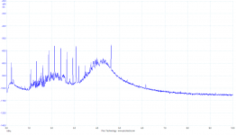
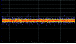
As far as I have full control over preamplifiers and amplifiers, I am not experiencing large spikes from mains that would not be attenuated by circuit PSR. I have a necessary design condition that the system must be immune to all switches, contactors, motors and another home appliances. There must be no audible sound when these are switched on, off or running. Regarding HF junk that comes from digital sources, its amplitude is up to tens of mV, so it is not neglegible. It may be compared to silent passages of classical music program regarding amplitude (-50dBFS), so the immunity to HF demodulation or intermodulation is definitely requested.
- Status
- Not open for further replies.
- Home
- Amplifiers
- Solid State
- Slew Rate