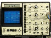
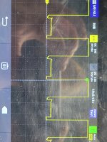
The drive circuit that drives the PS FETs must be at 0v (ground) for the FETs to be off (as they would be when the amp was not in operation. When in operation, it alternately drives each output of the 494 from ground to about 12v. Your appears to be driving from about 10v to 12v (instead of 0 to 12v, see attached). If you installed FETs with that drive signal, they would either fail immediately or the amp would draw excessive current because the two banks of FETs would be on at the same time.
Attachments
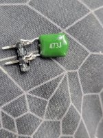
What were the markings on them?
Do you have replacement FETs, gate resistors and driver transistors on hand or will you have to order them?
Do you have replacement FETs, gate resistors and driver transistors on hand or will you have to order them?
I have the 3205s but I'm gonna have to order the resistors and fet drivers... the markings are 2t7 and 2x1...and I need to know where each one goes on the pcb.
If you only lift the transistors when testing (as below), you will be able to keep track of where they go.
The PNP drivers will be the ones with the collectors connected directly to ground.
Order at least one each of the 0.1uf, 0.047uf and 0.01uf film capacitors.
The 2t/2x drivers are:
Transistor marked 2T - mmbt4403
Transistor marked 2x - mmbt4401
Use 47 ohm gate resistors with the 3205s.
Do NOT install the PS FETs until you load test the FET drive with the film capacitor.
Attachments
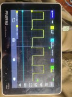
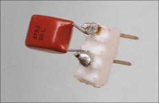
You connect the film capacitor across the gate and source pads for the PS FET and then check the signal on the gate pad for the FET with the capacitor. Without a load, you may see a perfect square wave, even if the drive circuit still has problems. With the loading capacitor, you get a curved waveform that should swing down to very near ground. The attached diagram shows what you will see (approximately) with each of the capacitors that were recommended. You only need to use one of the capacitors. I use the 0.047uf but the others are OK, as well. The first time doing this, you may want to use all three, just to confirm that you're seeing what you expect to see.
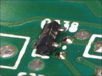
They vary in appearance. The following is one example. It's soldered to a piece of a header to make it easier to work with, more rugged and less likely to get thrown out as trash.
They vary in appearance. The following is one example. It's soldered to a piece of a header to make it easier to work with, more rugged and less likely to get thrown out as trash.
Attachments
Ok so I'm soldering on these fet drivers then load testing. And then solder on the ps fets. Then test again.....then drop in the rectifiers... thanks perry....I'll let you know if anything else arises after I solder on these fet drivers...oh yeah when load testing the fet drivers I should put the 494 back to normal right?
Don't install the FETs unless every PS FET location shows a perfect (as expected with a load).
Before installing the rectifiers, check the drive signal at the output locations. Disconnect the scope from the charger/power supply and operate from battery power.
With the output FETs in the circuit, you need no other load.
Before installing the rectifiers, check the drive signal at the output locations. Disconnect the scope from the charger/power supply and operate from battery power.
With the output FETs in the circuit, you need no other load.
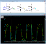
Alright perry we got trouble 6 Ps fets(three pairs) look like this not square.... the others that are square look like this under load...good I prasume....what's up with these 6 fets though?
Attachments
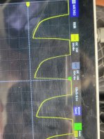

Where was the ground for your scope probe?
Go to 5v/div or move the ground for that channel down on the display.
Go to 5v/div or move the ground for that channel down on the display.
The scope, with no other connections to anything, has to have a reference. The ground clip for the probe has to be connected. Where did you have it connected?
- Home
- General Interest
- Car Audio
- Skar RP2000.1 issues