That's fine. it doesn't have to go to 0.000v DC.
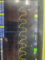
Look at the drive's purpose. It's to ultimately drive an N-channel enhancement mode FET. That type of FET requires about 3v to begin conducting. 10v is the sweet spot for driving them on. For them to stop conducting, the gate to source voltage will typically need to be below 2v. That drive signal is going well below that. You get about 3/4v of loss through the drivers but even adding 3/4v to the 0.1v of the 494, you're below 1v and the FETs will be completely off at that voltage.
Some amps have a resistor (R48 on your amp?) between the gate resistor input and ground to help the drive go closer to ground.
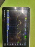
This is only one output. Did you find the reason for the doubled pulse on the other output.
Look at the drive's purpose. It's to ultimately drive an N-channel enhancement mode FET. That type of FET requires about 3v to begin conducting. 10v is the sweet spot for driving them on. For them to stop conducting, the gate to source voltage will typically need to be below 2v. That drive signal is going well below that. You get about 3/4v of loss through the drivers but even adding 3/4v to the 0.1v of the 494, you're below 1v and the FETs will be completely off at that voltage.
Some amps have a resistor (R48 on your amp?) between the gate resistor input and ground to help the drive go closer to ground.
This is only one output. Did you find the reason for the doubled pulse on the other output.
Had to be some bad soldered drivers I still have them out but I removed 2pnp and 2 npn that looked suspicious. And I was correct...I'm soldering them back on right now. unfortunatly my roommate threw away my new drivers away..thought it was garbage..urrrgggg...so I'm gonna hope some old ones I have are good..
Ok so I found that all is well on pin 9 and 10 for anout 1 min then it stops outputting the wave..are the bases and emitters on the npn and pnp suppose to have conductivity ? As in both bases are parallel and both emitters are parallel?
It must be another defective pwm controller...are the ka7500c's any good? Or should I only be using a 494?
They are both perfect for about 30 seconds the pin 10 goes crazy and it stops putting out wave.. I've went through 3 k7500s and a 494...I'm removing the drivers and trying again I've reversed engineered the drive and I don't understand what I'm not seeing... thanks perry
What do you mean by goes crazy? That's not very technical or specific.
Connect your scope to pin 10. Confirm with your multimeter that the DCV on pin 10 goes to 0v when you no longer see a waveform with your scope.
If that's what you find, leave your scope connected (watching for the signal to return) and measure the DCV on all pins of the 494. Does the signal on pin 10 return when you measure the voltage on any specific pin? Black probe on pin 7.
Either bad 494 or drivers... but the amp wont go out of protect.it workrd tjough for about 5min then pop smoke.....
What smoked, the power supply FETs?
Could you have a bad connection that's causing an intermittent problem?
If the FETs smoked, pull them, power up and monitor the drive while pushing on various parts of the board to see if the drive signal ever changes.
Were the FETs heating up?
Were you monitoring their temperature?
Could you have a bad connection that's causing an intermittent problem?
If the FETs smoked, pull them, power up and monitor the drive while pushing on various parts of the board to see if the drive signal ever changes.
Were the FETs heating up?
Were you monitoring their temperature?
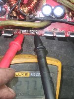
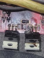
Well only two ps fets burn up and it looks like it burt the zener diodeas well but i have continuty between gate and source and drain and source pads it starts at 100ohm then the capacitors charge and it goes up to 600ohm. Is that normal? It would have surly burnt all fets if the drive signal was not norm correct?theres got to be a reson why these two burnt...drivers? Let me know thanks
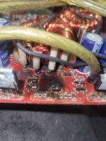
Attachments
I couldn't find anything wrong with anything.So I just soldered two new chips in and I guess i'm going to try it out
My question is why was the protect light staying on i undrounded pin 16 and resoldered it to its pad
Well im a retard..the protect light is red....i thought it was the blue one...and i have never used these "fet to sink clips"before and i didnt have not one clipped down tight....might have something to do with it.lol round 2 here goes.......
If you weren't monitoring the temperature, they may have overheated. They can overheat quickly, especially when the output stage is enabled.
Yes! I figured it out perry! I lost a resistor 2200 i googled it and it gave me a ohm of 2.2k wrong..damn google. It was 220ohm well i found a through hole 220 that is exactly 218ohms like the rest of the 2200s are 218ohms through it in and i did it! Thank you perry i understand the driver section of these amps now..simple...i can not thank you enough i will email you about your tutorial i want it...thanks perry!
For SMD, 4 digit resistors are 1% tolerance and the first 3 are the significant digits. The last is the multiplier. As an example, 4751 would be 4750 ohms.
- Home
- General Interest
- Car Audio
- Skar RP2000.1 issues