Any time you're checking a drive signal on an FET, the ground clip (best to use the short one that plugs into the end of the probe) to the source leg (leg 3) and the positive probe on the gate leg or pad.
It's critical that you use it on battery power when doing this on the output FETs.
It's critical that you use it on battery power when doing this on the output FETs.
I thought we were done with the supply. There is something wrong with both. The scope appears to be on DC coupling but the ground marker isn't aligning with either the top or bottom of the trace.
Post what you get with the ground for the scope on the ground terminal of the amp and the probe on the 12v terminal for the amp.
What's the DCV on pins 3, 4, 9, 10, 13 and 14? Black meter probe on pin 7 of the 494?
Post what you get with the ground for the scope on the ground terminal of the amp and the probe on the 12v terminal for the amp.
What's the DCV on pins 3, 4, 9, 10, 13 and 14? Black meter probe on pin 7 of the 494?
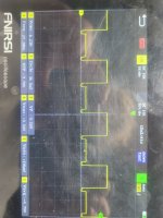
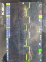
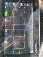
I got it grounded better.... i think..heres a pic of pin 9 and 10 on the scope.....9 being the better looking one..as for the voltages. 068v. .001v . 4.825v. 7.72v. 4.977v. 4.977v. ..I'm taking this new medication and it's making my eyes blurry up close I'm about to quit it because I can't handle it any more...
Attachments

Some drugs prevent your eyes from focusing closeup. If your vision is OK at longer distances, Walmart has reading glasses for about $5. Try several at the distance you need. I've been using them for about 20 years and would basically be blind for anything closer than about 6-8 feet without them.
The 494 is defective.
I'm assuming that you have pins 7 and 16 directly connected with a short length of wire. Grounding 16 to other points can cause strange problems like this.
The 494 is defective.
I'm assuming that you have pins 7 and 16 directly connected with a short length of wire. Grounding 16 to other points can cause strange problems like this.
Cool sounds like a Plan
I'll pop the 494 out of another amp I have to try it out... How did You know , the 494 was defective Was.
It the voltages I relayed.
I'll pop the 494 out of another amp I have to try it out... How did You know , the 494 was defective Was.
It the voltages I relayed.
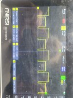
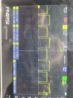
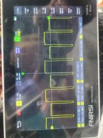
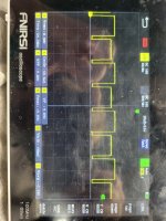
The IC has to ALTERNATELY drive the two banks of FETs for each power supply. This means that one bank will be on and the other off. The waveform on the left was what you should see.
The right waveform didn't turn off half of the time. To make sure that the scope waveform was likely right, I had you measure with the multimeter. The difference in voltage told me that the scope was likely right (and very unusual).
Using a multimeter (not definitive) you should see about 5v for each drive output when the FETs are out of the circuit. For a regulated power supply and the FETs (and rectifiers) in the circuit the multimeter readings will be equal (pin 9 to pin 10) but may be well below 5v.
Most all techs who do this work for years know as much or more. I did it for a bit over 30 years.
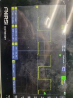
Measure the DCV on pins 9 and 10 again.
Are you sure that you didn't inadvertently reinstall the same IC?
Are you sure that you didn't inadvertently reinstall the same IC?
Last edited:
I unsoldered some of the drivers and the problem went away... I'm positive I installed a k7500 in place of the 494...
I didn't think about the drivers but I did for a pin 9-10 short but that would have made both pins look the same. Try to find the problem if you think it's a solder bridge.
- Home
- General Interest
- Car Audio
- Skar RP2000.1 issues