Member
Joined 2009
Paid Member
I've used 2N5401 and 2N5551 parts in other projects and found them to be very good. They do best when they have a decent voltage across their emitter-collectors (Keantoken has posted elsewhere on this forum that he found the BC parts are a better choice when operated at lower voltage due to the way they saturate/turn-onoff). It seems to me that in the GB150 the small signal devices operate with a good level of voltage across them at all times because the signal swings are relatively low compared with most amps due to the fact that the output MOSFETs are operated as gain devices so their input voltages have much smaller amplitude than the output..
fyi -When I was doing the pcb layout for TGM7 (essentially a GB15) I found that the pin-out for the BC parts in Eagle was different than in the data sheet for the parts I was buying from Digikey and I had to correct the Eagle footprint. This wasn't simply a case of which side the flat was, but the order of the pins which is much harder to fix.
fyi -When I was doing the pcb layout for TGM7 (essentially a GB15) I found that the pin-out for the BC parts in Eagle was different than in the data sheet for the parts I was buying from Digikey and I had to correct the Eagle footprint. This wasn't simply a case of which side the flat was, but the order of the pins which is much harder to fix.
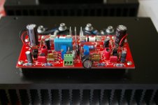
R28 and R29 appear to be empty. Are you omitting those?
I am still waiting for my outputs to arrive.
Looking good!
I am still waiting for my outputs to arrive.
Looking good!
Thanks! 🙂R28 and R29 appear to be empty. Are you omitting those?
I am still waiting for my outputs to arrive.
Looking good!
They're a new kind of audiophile grade resistors made of a meta-material that bends light making them invisible! 🙄LOL
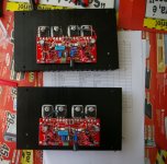
The board is very small and my resistors were big so I soldered them at the bottom side of the pcb.
Thanks Do!🙂Nice work Paulo!
Already tested and no smoke, only beautiful music!😀
Last edited:
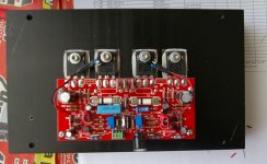
Sorry, I see now that you said that in pow #202. I see you have a couple pairs of transistors thermally coupled. Is that something that Greg advised?
Thanks, Terry
Thanks, Terry
No, it's not needed. Greg only advises to thermally couple the matched pairs if the amp is DC coupled (C9 linked) which is not my case. Anyway, I did it out of a perfectionist impulse. 🙂Sorry, I see now that you said that in pow #202. I see you have a couple pairs of transistors thermally coupled. Is that something that Greg advised?
Thanks, Terry
Sibilance
My build is almost finished but I have a problem. There is sibilance in female voices. You know, the "ssss" and "ttt". What could be the cause and how to fix it?
Thanks.
My build is almost finished but I have a problem. There is sibilance in female voices. You know, the "ssss" and "ttt". What could be the cause and how to fix it?
Thanks.
Member
Joined 2009
Paid Member
You need to be more specific as there can be many reasons. Did you compare two different amplifiers with everything else the same ? I find that sibilance is also a function of speaker cable and speaker. Do you have the feedback compensation capacitor installed - I use 10pF in my version.
My build is almost finished but I have a problem. There is sibilance in female voices. You know, the "ssss" and "ttt". What could be the cause and how to fix it?
Thanks.
If you have access to an oscilloscope see how the amplifier performs into 8 ohms with a square wave going through it.
If there are peaks or ripples on the corners of the waveform, you may need more high-frequency attenuation ie a slightly larger feedback capacitor.
This is a picture of a different amp, but I too am hearing too much sizzle on the high end. Is this what you are talking about with the wave form?


This is a picture of a different amp, but I too am hearing too much sizzle on the high end. Is this what you are talking about with the wave form?
Yes this is exactly what I'm talking about - in fact it's a lil worse than I pictured in my mind from what Paulo described.
See how it looks with a larger (ie 47pF) cap across the feedback resistor instead. Doesn't need to be silver mica, just use an NP0/X7R ceramic and see how you get on, if you feel like changing to a mica one once you've zeroed in on the correct value, it's up to you.
Last edited:
My build is almost finished but I have a problem. There is sibilance in female voices. You know, the "ssss" and "ttt". What could be the cause and how to fix it?
Did you use the BC 546 and 556 or the 2sa 970 and 2sc2240?
sorry my ignorances. What is the feedback compensation capacitor ?
regards kp93300
As I said, that is a different amp in the picture, not the SKA. I just recognized the description of the sound and wanted to know if I may use the same "fix".
Thanks, Terry
Thanks, Terry
sorry my ignorances. What is the feedback compensation capacitor ?
regards kp93300
A small capacitor installed in parallel with the feedback resistor.
It helps to counteract the amplifiers input capacitance, increasing the stability of the amplifier. It also creates high frequency attenuation (think low-pass filter) reducing the gain at higher frequencies.
This is a simplified explanation but I think it still works.
Frequency compensation caps are necessary in many cases and people should get into the habit of testing their amps (and preamps, opamps need compensating too) for instability using a square wave into a suitable load, then compensating with a cap.
Just to clarify, input capacitance isn't the only cause of instability and that adding large amounts of feedback capacitance isn't a cure-all for all problems stability related. Just that it is more often than not necessary to add some feedback capacitance.
As I said, that is a different amp in the picture, not the SKA. I just recognized the description of the sound and wanted to know if I may use the same "fix".
Thanks, Terry
Couldn't hurt to try it. Also if you have the design of your amp, try simulating it in LTSpice, TinaTI or Circuit maker and see how it behaves. It may be unstable due to other reasons, ie miller cap too small etc (assuming it uses miller stabilization, it could just as likely use something else).
regards
John (Oliphant)
I wonder if you guys (Paulo & Terry) have found an issue arising from those slight differences in Jim's boards v Greg's (& schematic)?
Yes, I have the original GB150D kit from Greg, stock parts, and it sounds very good without hint of sibilance. I'm using the same power supply with both amplifiers, the same source and speakers.You need to be more specific as there can be many reasons. Did you compare two different amplifiers with everything else the same ?
The one I'm building now, with Jims Audio pcb, uses different small signal transistors - 2SA970BL/2SC2240BL instead of BC546C/BC556C.Other difference is the use of a cheap decoupling caps (it was what I had at hand) - some obscure brand named "Samantha" (it's difficult to read the brand) - maybe this caps are causing the problem.
Other difference is the zobel cap - Evox Rifa PHE450 instead of Wima MKP4 (Greg recommends the Wima).
Everything else is the same - caps, resistors, etc.
The feedback cap is also the same - silver mica 5.6pF.
Actually, I just bought my first oscilloscope ever about a month ago. 🙂It's an entry level Rigol - DS1052E. I still playing with it and learning.If you have access to an oscilloscope see how the amplifier performs into 8 ohms with a square wave going through it.
I don't have a signal generator - I use the sound card to generate sinusoidal signals. Square wave it's not good - seems the card can't reproduce enough harmonics to give a decent square wave. It's all ondulated.
[FONT=Bookman Old Style, Book Antiqua, Garamond][/FONT]
Member
Joined 2009
Paid Member
Square wave it's not good - seems the card can't reproduce enough harmonics to give a decent square wave.
You have a free square wave generator in your oscilloscope. It's used for calibrating the probes. It's available on the metal tab at the bottom right corner of the front panel, just above the earth tab. It has a top-hat icon next to it.
- Home
- Amplifiers
- Solid State
- SKA GB150D now public domain...