Member
Joined 2009
Paid Member
I honestly doubt it's worth chasing the now obsolete/faked C-grade parts. Greg is the expert and he may feel otherwise but I don't think it will make a difference to the sound or reliability to use B-grade parts that are readily available. I'm willing to bet Greg a beer, mostly because I expect he'd be a hoot to have a beer with :-0
Now that the capacitors had time to break in I'm please to tell you that the amp is sounding impressively good!

 Outstanding dynamics, huge soundstage, impressive transparency!!!


To my ears it sounds just as good as the amp I built with Greg's pcbs! 🙂
Outstanding dynamics, huge soundstage, impressive transparency!!!
To my ears it sounds just as good as the amp I built with Greg's pcbs! 🙂
Last edited:
Member
Joined 2009
Paid Member
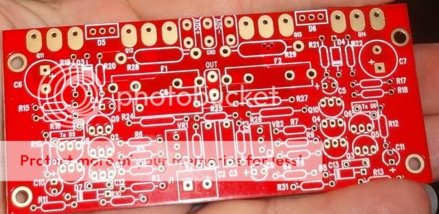
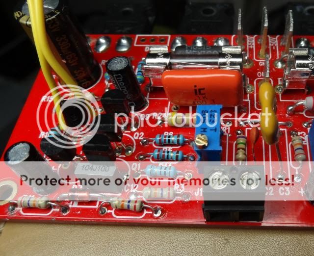
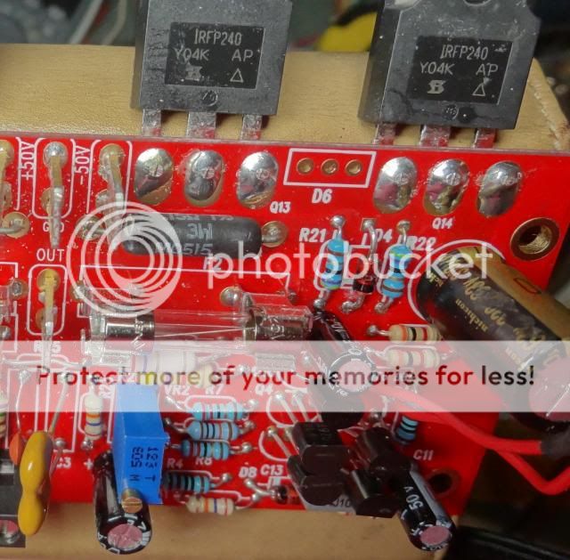
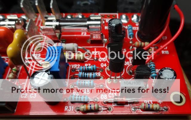
I'm having real issues with my build. I have been over and over the boards. I have measured every resistor at least 5 times. Checked the orientation of all the electros and transistors. I just went through and replaced the small transistors for the third time. I matched all of them as closely as possible and still I cannot get the amp to power up. I have it running through a light bulb and the amp will only come up to 3.8V on the positive rail and 4v on the negative. R10 is dropping almost almost 3V. I've run out of places to look so I am posting some pictures in hope that one of you eagle eyes will see something I am not. Thanks


An externally hosted image should be here but it was not working when we last tested it.


I'm hoping that you're not using BCs in there, right? The correct parts for Q1 to Q4 is Q1 are 2SC2240BL/2SA970BL or compatible.
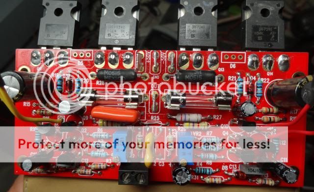
What about D5 and D6? You haven't installed those.
Do
What about D5 and D6? You haven't installed those.
Do
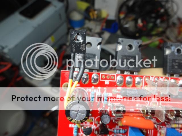
2CS2240BL Q1 & Q2 matched and 2SA970BL Q3 & Q4 matched. Sorry I didn't get D5 and D6 in the pictures. They are on the end of those wires.

I haven't build this amp yet but is there a pot for biasing and one for DC offset? If there's one for biasing maybe it is not turned on enough to fire up the mosfets?
Do
Do
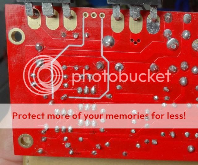
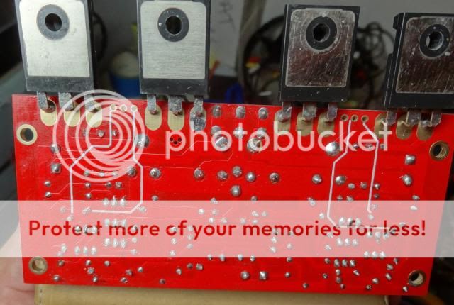
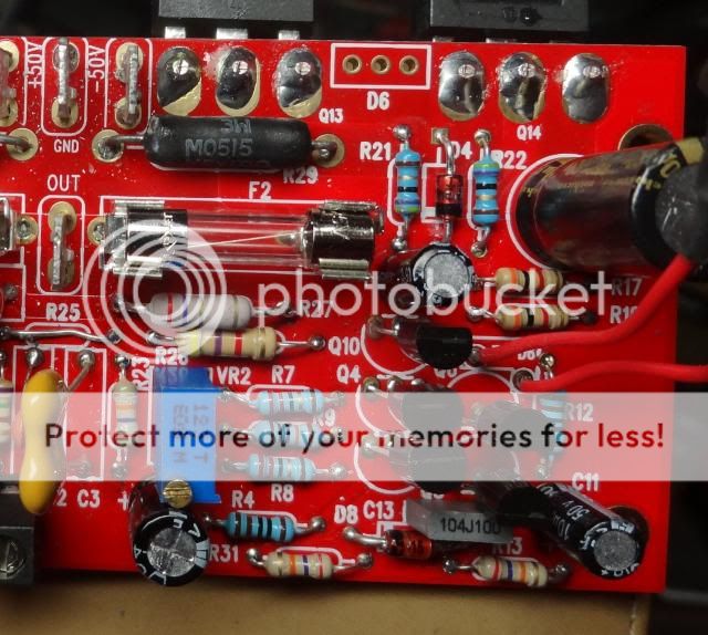
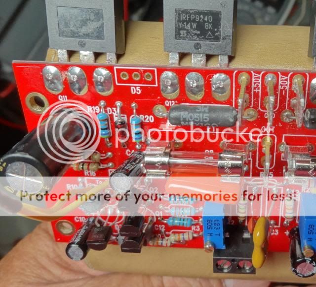
Terry, it looks like you have skipped soldering some of the mosfets legs on the bottom side of the pcb. Re solder all of them.
Chances are that you may have blown your output stages upper and lower. Watch out for ESD
Last edited:
You're right, they are all soldered on the top. Continuity has been checked on all of them. I can solder the bottom as well but I doubt it will change anything. I will solder them and report back.
Thanks
Thanks
What does that mean and how do I check for that. I have measured the outputs with and ohm meter and diode test and they seem to read fine. Tell me how to check and I will be happy to.Chances you have blown your output stages upper and lower 70%
Thanks, Terry
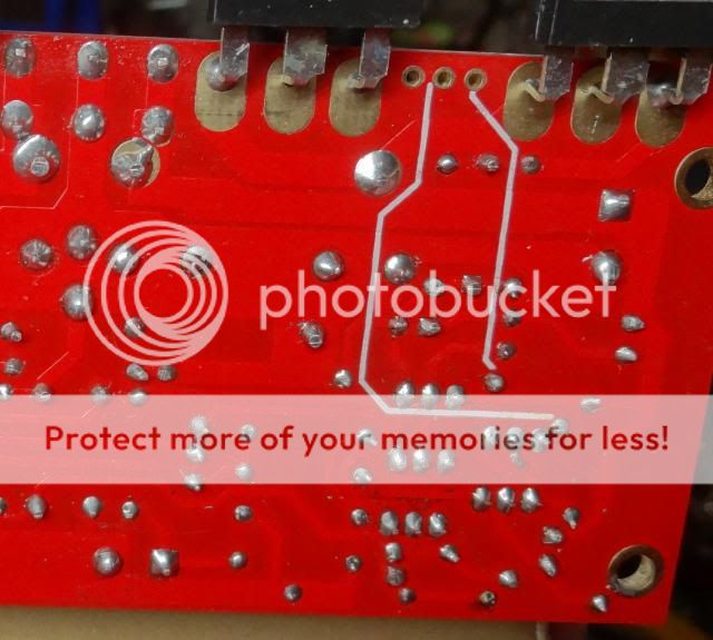
What mean with tracks on pcb bottom (picture n°2 and n°3)? Does it mean you have to put straps or does they relate a pcb tracks? If it the first case they are missing....Or they are here but not to use?
Marc
Edit : ok i see there's mod possibility...
Marc
Edit : ok i see there's mod possibility...
Last edited:
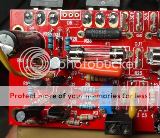
There are tracks at the bottom of the pcb that goes to the mosfets legs that are not soldered. Well that is what it looks like on the pictures. 🙂
Those white lines indicate the wires that go to the diode connected D5, D6 for temperature sensing. Terry appears to have connected them OK, see top view - red and yellow wires. These are bolted onto the mosfets when assembled, to sense temp.
I'm hoping that you're not using BCs in there, right? The correct parts for Q1 to Q4 is Q1 are 2SC2240BL/2SA970BL or compatible.
What about D5 and D6? You haven't installed those.
Do
I assume BC's are OK except for pinout? Or are there other changes to Jim's version to allow the change from BC's?
Bias pot full clockwise - full bias
Bias pot anti-clockwise - zero bias.
It's the oposite of Greg's boards.
Check the zener mod - is it right implemented? You also can use the RCR mod (less noise because no zener) - R11, R13=100k, R30,R31=330k, C12,C13=100nF.
Bias pot anti-clockwise - zero bias.
It's the oposite of Greg's boards.
Check the zener mod - is it right implemented? You also can use the RCR mod (less noise because no zener) - R11, R13=100k, R30,R31=330k, C12,C13=100nF.
When you say the amp doesn't come up. What specifically; No bias at all or the bias comes up but not enough?
Something else?
Something else?
Member
Joined 2009
Paid Member
There shouldn't be 3V across R10, if you are measuring this kind of drop you have 3mA flowing through the current source whereas it should be more like 1/2 mA - at least in my version that is what I would expect.
If the power rails won't come up - too much voltage drop across the bulb or too much current draw by the amp.
As Paulo says, maybe you have the bias pot adjusted to full-open-throttle which is encouraging the output devices to suck a lot of current and pull the rails down through the voltage drop across the series bulb.
- Home
- Amplifiers
- Solid State
- SKA GB150D now public domain...