In Jim's schematic also isn't coupling capacitor and input resistor..
I have PCB's from Greg as well as Jim. Both have input resistors (setting input impedance).
100k resistor and 4,7 uf capacitor is missing, when I comparing both schematic.
You mean input capacitor with a discharge resistor connected from input to ground? Both these components can be placed outside of PCB.
Member
Joined 2009
Paid Member
Jim's boards are an unauthorized knock-off so it's a case of buyer-beware.
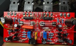
Greg's boards are proven so that's the safest option.
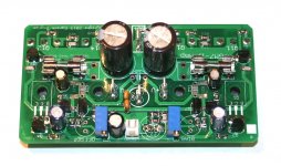
The most 'modern' boards which don't need mods or fly-wires but do make use of surface mount resistors, are my boards:
http://www.diyaudio.com/forums/solid-state/239418-tgm7-amplifier-based-greg-ball-ska.html
The pcb files are in post 195
Greg's boards are proven so that's the safest option.
The most 'modern' boards which don't need mods or fly-wires but do make use of surface mount resistors, are my boards:
http://www.diyaudio.com/forums/solid-state/239418-tgm7-amplifier-based-greg-ball-ska.html
The pcb files are in post 195
Attachments
Bigun,
Nice PCB's!
Just to clarify. I bought both because I wanted to support Greg. Jim's PCB is double weight (copper).
Nice PCB's!
Just to clarify. I bought both because I wanted to support Greg. Jim's PCB is double weight (copper).
I just built the amp ( but with other MOSFET) using Jim' pcb and I also needed to use 47-100pf on c-b of Q9/Q10 to get a perfect square wave until max swing output -as per Bigun schematics. I also have the Zener mod. Since I had to adapt for different MOSFET I had to modify other parts value as well. Therefore, you may have to try maybe different options than mine...
Fab
Fab
Last edited:
For clarify, I bought PCB from Jim's because is for me easiest way. I am not sure, that is possible to order PCB only from Greg..
I´ll try TGM7 like next .. but I have to firstly finished gb150,VSAA and DX Super A 😀
I´ll try TGM7 like next .. but I have to firstly finished gb150,VSAA and DX Super A 😀
I am not sure, that is possible to order PCB only from Greg..
It is. Have a look at Greg's order page.
So, now is all set like in schematic , which send Paulo.. still same result. I have to watch signal, where is point of distortion..
Bigun is right. If you want full support you should buy the autorized Greg's boards.Jim's boards are an unauthorized knock-off so it's a case of buyer-beware.
Greg's support is second to none!
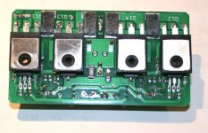
I have build the SKA severeal times most of them with Greg's boards. I have a recent build with Jim's boards. Jim's boards have a feature that I needed in this build that Greg PCBs don't offer - mounting holes. The early Greg boards had mounting holes but they were removed to allow space for C10 and C11. I needed to mount the PCBs parallel to the heatsinks so I couldn't use Greg's. I must admit Jims are gold plated and thicker, better quality. But they omiiss a very i portant connection: signal ground to main star ground. And they have the outdated obsolete zener mod that shouldn't be there.
So, if you nedd to mount the boards parallel to heatsink - use Jim's boards. If don't need this feature and want the best support on the planet - use Greg's boards.
Jim's boards are an unauthorized knock-off so it's a case of buyer-beware.
I keep seeing this. Greg released the design to public domain. The design should be fair game. If it is not, then all boards except for the ones Greg produces are "unauthorized knock-offs".
There is nothing wrong with Jim's boards. I have built 4 and they work. The only issues I had with them were self inflicted. If you build them per Jim's BOM they will work. Note: the schematic attached in post #613 will not work on Jim's boards. Jim's uses 2SC2240BL for Q1 & 2. The pinout is different.
Mine work fine with the Zener installed.
Attachments
My mistake. I forgot to say where you see BC's you should read 2S. Otherwise the schematics works. I was addressing the "mods" issue. If you use C10 and C11 you should remove the zener. Choose between these capacitors and the "mods". Of course with the zener (or RCR) mod in place the amp still works but "still works" it's not good enough for me. You'll have better performance if you ditch the mods and use C10 and C11 and replace the two 27k resistors of the mod with a 100k . See the schematics I attached in that post. If you insist in the zener please remove C10 and C11.There is nothing wrong with Jim's boards. I have built 4 and they work. The only issues I had with them were self inflicted. If you build them per Jim's BOM they will work. Note: the schematic attached in post #613 will not work on Jim's boards.
Stillforgiven,
Where is you signal ground wire? Can someone please tell Jim to put a hole for this wire in the next batch of PCBs he'll produce? And now we are at it please use a short wire and run it against the chassis away from power wires and directly connected to star ground. I can't stress this enough! Oscillations may happen without this dedicated wire.
Last edited:
Member
Joined 2009
Paid Member
The early Greg boards had mounting holes but they were removed to allow space for C10 and C11.
I don't like mounting holes either, it's already enough trouble lining everything up on the heatsink. My pcb's don't need them, the boards are small and compact and are bolted to the heatsink through the power devices (with clever use of the drivers as 'spacers' and thermal feedback).
There is nothing wrong with Jim's boards. I have built 4 and they work.
I see your problem there Terry, the fuses have diagonal wires inside them, they need to be straight 😛
Bigun,
You're boards are different. With your boards I don't need mounting holes because I can use the Output devices for that role. In Greg's boards that is simply not possible or the board will touch the heatsink and short circuit.
You're boards are different. With your boards I don't need mounting holes because I can use the Output devices for that role. In Greg's boards that is simply not possible or the board will touch the heatsink and short circuit.
Last edited:
My mistake. I forgot to say where you see BC's you should read 2S. Otherwise the schematics works. I was addressing the "mods" issue. If you use C10 and C11 you should remove the zener. Choose between these capacitors and the "mods". Of course with the zener (or RCR) mod in place the amp still works but "still works" it's not good enough for me. You'll have better performance if you ditch the mods and use C10 and C11 and replace the two 27k resistors of the mod with a 100k . See the schematics I attached in that post. If you insist in the zener please remove C10 and C11.
Stillforgiven,
Where is you signal ground wire? Can someone please tell Jim to put a hole for this wire in the next batch of PCBs he'll produce? And now we are at it please use a short wire and run it against the chassis away from power wires and directly connected to star ground. I can't stress this enough! Oscillations may happen without this dedicated wire.
I have a couple boards on the shelf. I will try pulling the Zeners, C12/13 and R11/13. I will install 100k in R30/31 and give it a listen. I didn't install a ground wire to the input. R14 provides a "lifted" ground for the input. Why would I want to take the chance of adding a ground loop by adding a separate wire? If anything a jumper could be installed in place of R14. What is your reason for running a separate wire?
I have a couple boards on the shelf. I will try pulling the Zeners, C12/13 and R11/13. I will install 100k in R30/31 and give it a listen. I didn't install a ground wire to the input. R14 provides a "lifted" ground for the input. Why would I want to take the chance of adding a ground loop by adding a separate wire? If anything a jumper could be installed in place of R14. What is your reason for running a separate wire?
Because it's a path for positive feedback. In his forum Greg stresses this issue very much, he says we risk oscillation if this wire is not used.
Don't remove the input ground wire as it is the primary connection for the input and feedback grounds on the amp module to the star ground.
Last edited:
Hi Paulo,
I removed the zener and associated parts on one board and installed the 100k resistors. I really don't see any differences either on the scope or DMM between the two. I suppose if I were building another I would just go without the zener since it takes less parts. I now remember one thing I didn't like about these boards. The holes are pretty tight and with through hole plating if is really a job removing parts. 😉
You are right about the input ground as well. I was hearing a little oscillation and one channel was running hot. I hooked up jumper cables from the input ground to star and it went away. I guess I have just been lucky with the SKA I have mounted in a case. It has been playing perfectly for over a year. I'm going to open it up and install some ground wires just to be safe.
Thanks, Terry
You have to remove the RCR mod. Both the zener mod and the RCR mod are obsolete. They've been replaced by the presence of C10 and C11. Build exactly as the released schematics. Also don't forget to connect the signal ground to main star ground with a dedicated wire! Unfortunately Jim's boards don't have a hole for that connection.
What is wrong with the Zener mod?
The officially published schematics has R14 of 10 ohms between SG and power ground. I had to lower R14 to 2.7 ohms to remove motorboating ( one channel).
Fab
I may try a smaller value there as well too see if I can remove that extra ground wire. I don't see any difference between the two boards on my scope. No change in sound either from what I can tell. I've had them playing for a couple hours now. Sounds good and no issues.
- Home
- Amplifiers
- Solid State
- SKA GB150D now public domain...