Hi Maxwell,
You need a better heatsink for this amplifier.
Square is good in my build so you must have a problem with yours. Did you connect the signal ground with a dedicated wire to main star ground? Jims boards lack a hole for this very important connection!
You need a better heatsink for this amplifier.
Square is good in my build so you must have a problem with yours. Did you connect the signal ground with a dedicated wire to main star ground? Jims boards lack a hole for this very important connection!
Your misuse of Grn/Yel is ill advised.sounds good 🙂
Save Grn/Yel for Chassis to PE only.
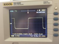
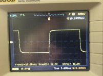
Some of the rounding of the 10kHz will be due to the RF filtering on the input.
What have you fitted?
You may have to move this up in frequency by a decade or more to get useful info on stability testing.
The lower Slew rate in the negative direction is unusual.
What have you fitted?
You may have to move this up in frequency by a decade or more to get useful info on stability testing.
The lower Slew rate in the negative direction is unusual.
OK guys, I know about wiring color, it´s cosmetic detail.. 😀 What exactly influences SR ? I´ll check schematic, and also compate jims vs Greg...
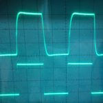
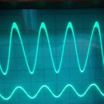
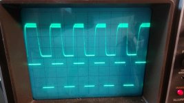
I did some measurements.. It seems, that distortion of square depend on level output source.. the higher the level the greater the signal distortion and the transient also appear ...pictures are for same frequency, with different level..
Attachments

Hmm...
As I know, you have also Jim's PCB.. did you use his schematic? I already implemented RCR mode, this is only one change...
As I know, you have also Jim's PCB.. did you use his schematic? I already implemented RCR mode, this is only one change...
You have to remove the RCR mod. Both the zener mod and the RCR mod are obsolete. They've been replaced by the presence of C10 and C11. Build exactly as the released schematics. Also don't forget to connect the signal ground to main star ground with a dedicated wire! Unfortunately Jim's boards don't have a hole for that connection.
OK, I´ll try remove RCR mode and put back zener...will see 😀
NO! Don't put back the zener! The zener must go! Only stays a 100k resistor as the shematics!
Attachments
In Jim's schematic also isn't coupling capacitor and input resistor..
Maybe Jim forget them too... You can DC couple the amp or mix couple but if you do that you must assure your source is DC free.
In rhe original form the SKA is a mixed coupled amplifier. It has a NFB capacitor but no input cap. It's of course safer to use both caps.
See the schematics of my other post. Follow it because it's the right one.
- Home
- Amplifiers
- Solid State
- SKA GB150D now public domain...