Thanks cogitech. Did I read somewhere that you went with Transcendar OPT's? Is your SSE up and running?
Thanks cogitech. Did I read somewhere that you went with Transcendar OPT's? Is your SSE up and running?
Yes, I did go with Transcendars. Hoping to get some time to finish up my build this weekend - or at least run it through initial power-up and testing.
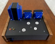
I installed and wired up the choke and OPT's.
I'll give my eyes and mind a rest and tackle the PT when I'm fresh.
If anyone sees a glaring (or, minor) error, please let me know!
cogitech, I probably won't power up until the weekend, either. I need to hit HomeDepot and buy the parts to make a dim-bulb tester. Like every new hobby, you can spend more on tools and equipment than on the thing you're building.
Thanks.
Attachments
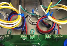

Wiring looks perfect to me. I assume you left the OPT leads long for initial testing and then you'll shorten them up later?
Jones mentions several times in his book that output tubes should be close to OPTs (wiring as short as reasonably possible), but like you say, if there is no hum or other issue then what's the harm?
OK, well, I shortened the primary leads on the OPT's. I'll test it before messing with the speaker leads.
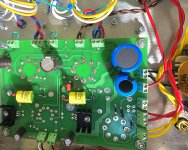
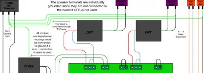
I found a huge mistake from earlier. I had the choke attached to the wrong terminals!
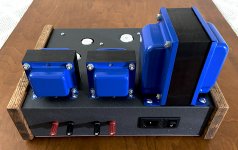
I wired up the PT. I'm assuming the 6.3V center tap is not used. I tucked it away.
There's clearly an art to chassis layout that can only come from lots of experience - that I don't have. But, I've managed to learn some things for next time.
The day of reckoning for this project is near. I'll spend a couple of days triple checking everything. The funny thing is that it's gotten more and more challenging the closer I've gotten to the end.
I found a huge mistake from earlier. I had the choke attached to the wrong terminals!
I wired up the PT. I'm assuming the 6.3V center tap is not used. I tucked it away.
There's clearly an art to chassis layout that can only come from lots of experience - that I don't have. But, I've managed to learn some things for next time.
The day of reckoning for this project is near. I'll spend a couple of days triple checking everything. The funny thing is that it's gotten more and more challenging the closer I've gotten to the end.
Attachments
Cut those lase, you can cut on those sharp edges.
Hi potepuh, I'm not certain what you're referring to. Thanks.
Might be worth trying satin rattlecans. Just a quick spray from a distance to build up a speckled fine finish. Repeat wait a few minutes and repeat until you've built up a deep texture. Hides a multitude of sins.
New paint finish on platter. | Simon Clarke | Flickr
New paint finish on platter. | Simon Clarke | Flickr
Thanks potepuh. I removed the zip ties (laces); they were pretty tight. After it's up and running I might just go ahead an shorten the OPT secondary leads like I did with the primary wires.
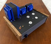
Thanks sq225917. That platter looks amazing. I actually went back and hit the chassis with a couple more coats of the texture spray after posting the previous pic. I'm happy with it now.
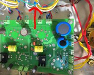
I also wired in a CL-90 on the "L" terminal of the IEC (I was previously told here in this forum to attach it to that point).
I've checked everything for continuity to the chassis: RCA jacks, speaker terminals, volume pot, transformers, and IEC ground pin (the one on the outside that the AC cable connects to). All is good. I wiggled every resistor, capacitor and other parts; all have solid solder joints. Again, everything looks go to go. I just need to make a dim-bulb tester...
Thanks sq225917. That platter looks amazing. I actually went back and hit the chassis with a couple more coats of the texture spray after posting the previous pic. I'm happy with it now.
I also wired in a CL-90 on the "L" terminal of the IEC (I was previously told here in this forum to attach it to that point).
I've checked everything for continuity to the chassis: RCA jacks, speaker terminals, volume pot, transformers, and IEC ground pin (the one on the outside that the AC cable connects to). All is good. I wiggled every resistor, capacitor and other parts; all have solid solder joints. Again, everything looks go to go. I just need to make a dim-bulb tester...
Attachments
Last edited:
I found a huge mistake from earlier. I had the choke attached to the wrong terminals!
Holy crap! Well now you know you can't trust me any more than you can trust yourself! 😱
I totally missed that, too.
Well, we're looking at the underside of the board! I should have been following George's underside wiring diagrams.
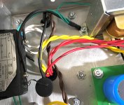
And, another mistake: I could swear I wired the CL-90 to the hot "L" terminal on my IEC; I even used a magnifying glass to make sure. Still, I managed to solder it to the "N" terminal. Like the choke, it was a very easy fix. But, it goes to show that I really need to triple-check my work and go slow.
BTW, I put the amp on a digital scale. It weighs 24.4lbs without the tubes!
The polarity thing on AC always baffles me, to be honest. I am willing to bet it would have worked perfectly with the CL-90 on the N terminal.
I am saying this so someone jumps in and corrects me with a thorough explanation of why polarity matters in this AC scenario. 🙂
I am saying this so someone jumps in and corrects me with a thorough explanation of why polarity matters in this AC scenario. 🙂
If the cl-90 opened up you would have 120 volts floating around. A big surprise if you are doing a quick "WTF"
I've checked everything for continuity to the chassis: RCA jacks, speaker terminals, volume pot, transformers, and IEC ground pin (the one on the outside that the AC cable connects to).
Are you sure you want the RCA jacks and speaker posts to be tied to chassis ground?
Thanks mike567. Glad I took the time to move it to the line terminal.
Hi Vunce, the jacks and terminals themselves are isolated from the chassis. The RCA jacks are using those plastic washers that fit into the chassis holes. The speaker binding post bodies are plastic. There are no metal parts touching the chassis.
Sorry, what I should have said was that the ground wires that George indicates in his diagrams have good conductive connections to the star ground.
Are you sure you want the RCA jacks and speaker posts to be tied to chassis ground?
Hi Vunce, the jacks and terminals themselves are isolated from the chassis. The RCA jacks are using those plastic washers that fit into the chassis holes. The speaker binding post bodies are plastic. There are no metal parts touching the chassis.
Sorry, what I should have said was that the ground wires that George indicates in his diagrams have good conductive connections to the star ground.
Attachments
Ahh!! Very well then 😉
Your SSE is coming out really nice.
You should be powering up soon, good luck!

Your SSE is coming out really nice.
You should be powering up soon, good luck!
- Home
- More Vendors...
- Tubelab
- Six Year SSE Project Nearing Completion