or send it to be repaired, or sell it as is, not 100% working, its not such amp, that would be worth spending amost any money on it
I don't know...maybe i'll sell it but for the moment i prefer to keep it because i have not amp to put on my subwoofer.
When i'll have enough money i will buy a real amplifier and not a cheap amp like sinus live
When i'll have enough money i will buy a real amplifier and not a cheap amp like sinus live
as I see it, you still don't have amp, I'm not sure if you'll gonna put SLA on your subs any time soon, if even again
For the moment i have a new car and tomorow i'll put the speakers on front door with my soundstream reference 500S on it and in the futur or if there is not enough bass i'll try will the sinus live amp but not sure...
otherwise i search an audiophile amp for my sub who can deliver 900Wrms at 2ohms
do you think that amp is good ?
Grandes marques autoradio sono navigation - DLS CLASSIC CAD15 amplificateur mono classe D en vente sur chila-audio.com - promotions car audio subwoofer sono tuning ampli gps
Thanks
otherwise i search an audiophile amp for my sub who can deliver 900Wrms at 2ohms
do you think that amp is good ?
Grandes marques autoradio sono navigation - DLS CLASSIC CAD15 amplificateur mono classe D en vente sur chila-audio.com - promotions car audio subwoofer sono tuning ampli gps
Thanks
Hello 🙂
I've got news about the sinus live amp
I change my car with a new and the pop noise in the new car is less audible and sometimes i can't here it 😕
It's really strange because on the power supply 13.8VDC i can here the pop noise and now the pop noise seems disappear😕
If you can explain me that please ?
Thanks in advance
Hello
Now the pop noise seems not present 😕 i can hear a little noise but not a big "pop" like before
I'll do measurement tomorrow to have the voltage on the terminal speaker when and i hear the noise....
but now the sound seems bad, bass are not clear it's really bad i don't know why and the sound seems have more power 😕
If someone can help me please because i havent" money to buy other amp for the moment 🙁
Thanks in advance 🙂
Hello
I have mesured with the speaker connected:0.343mv and without the speaker i have 1.332v
the value have change and i don't know why 😕 but now the sound is more power but it's a poor quality 😕
Can you help me please ?
Thanks in advance 🙂
I have mesured with the speaker connected:0.343mv and without the speaker i have 1.332v
the value have change and i don't know why 😕 but now the sound is more power but it's a poor quality 😕
Can you help me please ?
Thanks in advance 🙂
I think it would be necessary to have a scope to find a problem that caused a distorted signal. You could go back through the amp and confirm that all of the audio op-amps have the proper positive and negative power supply voltages on them. You could also check the rail voltage to confirm that the output transistors have both positive and negative voltage.
Hello Perry
youpi you are here!🙂
why you do not live in France 😀 ?
if you were my neighbor it would be cool 😎
I'll re-test the amp today or tomorrow "when i'll have a little time".....
I also see a condensator with glue or something on it, he seems to flow on the top 😕
for the scope can you tell me if i can buy this please? because i haven't a lot of money and i prefer to have a new product not already used...
Oscilloscope 610/2 10 MHz sur CONRAD, Oscilloscopes monocanaux analogiques, Oscilloscopes
Thanks a lot for your help Perry 🙂
That scope should work well enough but there's still no guarantee that you'll be able to repair it even with a scope. Can you borrow one?
I don't generally recommend using software/soundcard based scopes but that may be sufficient to see the distortion on the output. There's a danger of damaging the soundcard so you would need to build a protection circuit if you were going to try to use your computer.
I don't generally recommend using software/soundcard based scopes but that may be sufficient to see the distortion on the output. There's a danger of damaging the soundcard so you would need to build a protection circuit if you were going to try to use your computer.
No i can't borrow a scope 🙁
i'll try to buy a scope in the coming months or the more simple is changing the amp 🙄
i'll try to buy a scope in the coming months or the more simple is changing the amp 🙄
Hello Perry
I've got knews i know why the pop noise is less important in my new car 🙂
In fact having a new car has nothing to do with this problem.
I modify the set up and when i don't use the subsonic potentiometer, the pop noise is at 2.7 vdc and when i use the subsonic filter, the pop noise seems less important and almost inaudible i can mesure it at 0.9vdc at the middle setting and when i set it to 50hz "to the max" i have 0.41VDc
I think this can help you to help me resolve the problem on this Amp ?
So what can i do now?
Thanks in advance perry
🙂
You could try measuring the DC voltage on the output pins of all of the op-amps in the audio section of the amp to see if any have DC on them. None should have more than about 0.01v DC.
Thanks Perry 🙂
but 😱 can you remember me please how can i mesure the output voltage ?
"my bad english make problem to understand..sorry" 😱
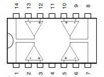
if i understand on all op-amps, the output is pins: 1 ; 7 ; 14 ; 8
Am i right ?
if it's ok where i put the negative black wire of my multimeter if the red wire is "for exemple" on pin 1 ? i put it on the negative ground 12 volt ?
I use the schematic pin configuration that you give me "please see attachement"
but 😱 can you remember me please how can i mesure the output voltage ?
"my bad english make problem to understand..sorry" 😱
if i understand on all op-amps, the output is pins: 1 ; 7 ; 14 ; 8
Am i right ?
if it's ok where i put the negative black wire of my multimeter if the red wire is "for exemple" on pin 1 ? i put it on the negative ground 12 volt ?
I use the schematic pin configuration that you give me "please see attachement"
Attachments
to measure i put the black wire of my multimeter on the negative output speaker and the red wire of my multimeter on all pins of the circuit, like last time?
for the AOP U3 i have
Pin 1: 0
pin 2:0
Pin 3: 0
pin 4: 12.8
Pin 5: 0
pin 6: 0
Pin 7: 0
pin 8: 7.8mv
Pin 9: -1.1mv
pin 10: 0
pin 11: -12.8
pin 12: 0
pin 13: 0
pin 14: 180 mv and grow up slowly...
The u2 AOP
Pin 1: -1.7mv
pin 2: 0V
Pin 3: 0V
pin 4: 12.8V
Pin 5: 19.2mv
pin 6: 19.3mv
Pin 7: 32.2mV
pin 8: 0V
Pin 9: 2mv
pin 10: 0V
pin 11: -12.9V
pin 12: 0V
pin 13: 0V
pin 14: -1.2mv
the u1 AOP
Pin 1: 12mv
pin 2: 1.8mv
Pin 3: 0
pin 4: 12.8V
Pin 5: 0
pin 6: -1.9mv
Pin 7: 32.3mV
pin 8: 19.1mv
Pin 9: 11.5mv
pin 10: 11.2mv
pin 11: -12.9V
pin 12: 00.1mv
pin 13: 00.4mv
pin 14: 5.4mv
That's it when i write 0 generaly my multimeter mesure 00.1mv that's for all Aop
So I think you can help me Perry 🙂
thanks a lot in advance 🙂
- Status
- Not open for further replies.
- Home
- General Interest
- Car Audio
- SinusLive SL-A1500 help needed.