hello Workhorse, i have studied it last night for a bit. i have done it.
the simulation works with great results.
please take a look at the schematic . it is some posts up.
thanks a lot
Savu Silviu
Sims look fine😉
Found some problems in BTL_UCD_REV1.jpg.
LT1016 has maximum 7Vdc operating voltage.
So i corrected a bit the power supply for LT1016 and the logic side of the IR chips.
All seems ok now.
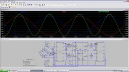
Vdc - 190V
SW FQ - 440KHz
P out RMS -4KW
p out Peak - 8KW
THD - 0.1% at 1Khz 2Vpp input
Updated schematic attached,
Savu Silviu
LT1016 has maximum 7Vdc operating voltage.
So i corrected a bit the power supply for LT1016 and the logic side of the IR chips.
All seems ok now.
Vdc - 190V
SW FQ - 440KHz
P out RMS -4KW
p out Peak - 8KW
THD - 0.1% at 1Khz 2Vpp input
Updated schematic attached,
Savu Silviu
Attachments
Last edited:
Hello Luka,
Hope that I will have the time to actualy build it. It could be a nice project.
Just needs undervoltage, overvoltage and overcurent protection, i have to figure out how to make a limitation to the input signal to avoid clipping and also the most important thing is to make adjustable dead time controlled by the output curent (this will be realy tricky) so that i will allways keep it working to the highest condition regarding THD vs power.
PS: just simulated it with 2 ohm load.
8 KW rms, 16 KW peak, 0.5% THD, 135W disipated per mosfet.
in the 4 ohm simulation the disipation is only 39W per mosfet.
Then again this is only a simulation.
But the idea of actualy building it is begining to push me to make free time for this project.
Attached is the 2 ohm load simulation printscreen
Best regards,
Savu Silviu
Attachments

one could hope that it would work in real life too, but driving 2R is pretty damn hard, with one set of fets in full bridge
savu!
I'm almost sure that the temperature-dependent channel resistance is not implemented, and this involves 2-2.5 times more conduction loss.
Not only average dissipation counts, because at low frequency the chip temperature can follow the power fluctuations more-or-less.
I don't know if you used a realistic modell of the body diode, but if yes, then still at high temperature it works worse.
hello Pafi,
While designing and simulating something like class d amps in lt spice i try to reduce as much as possible this temperature reading. beeing a simulation after all i know that the numberes might be wrong. but if i get them as low as possible it will make life easier when building it and testing it.
I am seriously thinking of actualy building this thing and feeding it with 180Vdc just to be on the safe side of the IRFB4227 (200V drain to source maximum).
Do you have any tips to share because i am planing to design the pcb in the next days.
Best regards,
Savu Silviu
Hello guys,
does anyone know a faster mosfet driver than ir2110?
my comparator has 4,5nS delay so i would like a driver faster than ir2110 so that i can eliminate group delay as much as possible.
Regards,
savu
does anyone know a faster mosfet driver than ir2110?
my comparator has 4,5nS delay so i would like a driver faster than ir2110 so that i can eliminate group delay as much as possible.
Regards,
savu
Seems that analogspiceman has done it again ... or? ..... savu, can you post the IR2110 LTSpice model ...
Thanks in advance
Baldin 🙂
Thanks in advance
Baldin 🙂
thanks luka,
i have to use tc chips with 6n137 optical isolated cmos driver.
i'll give it a try after i get to work.
also Baldin,
i will post the model once i get to work.
best regards,
savu
i have to use tc chips with 6n137 optical isolated cmos driver.
i'll give it a try after i get to work.
also Baldin,
i will post the model once i get to work.
best regards,
savu
The asy file is only the symbol; he'll also need the IR2110.asc file, to be in the same folder with the .asc file in which the .asy is used 
The asy file is only the symbol; he'll also need the IR2110.asc file, to be in the same folder with the .asc file in which the .asy is used
updated ...
sorry for the error.
regards,
savu
Attachments
Hello guys,
does anyone know a faster mosfet driver than ir2110?
my comparator has 4,5nS delay so i would like a driver faster than ir2110 so that i can eliminate group delay as much as possible.
Regards,
savu
Hi Savu
Very good your project.
you have any news about it? already designed the PCB?
one thing is fact, in my opinion to get 8KW RMS at 2 Ohms with this switching frequency, it would need at least 16 Mosfets IRFP4227 Considering the temperature and conduction losses.
in relation to the dead-time, as the UCD has feedback after the filter output, why not use a fixed deadtime through logic circuits?
Another interesting point, would you put in the output of Gate Driver a totem-pole with two common transistors to increase the output current in driver because you will need ..
Hugs,
Cleber
Hello edicleberyahoo,
the amp is only a simulation. in reallife it would be used for 4 and 8 ohm loads to arround 3Kw rms with 2 paraleled irfb4227 instead of one for minimazing the temperature. (version without active dead time regulator)
i found a simple solution to vary dead time acording to the output curent.
just need to test it and to opticaly insolate it from the power stage.
the project as it is, is only in LT spice so i intend to design a pcb as soon as i can figure out the best aproach regarding efficeiency and also minimum total propagation delay. for the time being i have a stable simulation that outputs 3.5KW rms with 0.19% THD, fullbridge with 4 irfb4227 that dissipate only 20W a piece on a 4 ohm load.
the only problem is that the dead time regulator used is not my design so it might be a problem if i use it (in case this turns out to be a rock solid pro amp).
regards,
savu
Hello All,
Someone would have any idea?
to make a UCD with the frequency of switching in 100Khz with limited response to 5kHz?
I liked the topology UCD but it would need to use low frequency, it is possible?
Tks...
Cleber
Someone would have any idea?
to make a UCD with the frequency of switching in 100Khz with limited response to 5kHz?
I liked the topology UCD but it would need to use low frequency, it is possible?
Tks...
Cleber
- Status
- Not open for further replies.
- Home
- Amplifiers
- Class D
- Single supply bridge UcD, referencing the signals