If you SPICE it you'll see a fairly large component of the switching frequency (resulting from the post-filter ripple, and the NFB path attenuation) but a low component of the audio signal.
Ouroboros!
Good explanation, but this part is not exactly correct. They must be more or less equal at maximal input signal. (Since comparation of these makes PWM operation.)
Cro maniac!
Both audio inputs are balanced by a corresponding divided output signal with opposite phase (because of negative feedback), hence the cancellation at comparing points.
Aaah, what stupid questions I ask !
So trivial !
I keep summing the signals, thinking wtf?, and forgetting it is the NEGATIVE (once again: NEEGATIVE) feedback.
 🙄
🙄 
So, TL3016 will do just fine 🙂
Guys, thx for help and for being patient with me.
So trivial !
I keep summing the signals, thinking wtf?, and forgetting it is the NEGATIVE (once again: NEEGATIVE) feedback.
🙄 So, TL3016 will do just fine 🙂
Guys, thx for help and for being patient with me.
Just made the amp
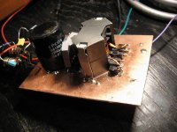
I finally took the time to make the amp. The board is 2-layer with ground plane on bottom. Elements are mostly smd. When routing the board I took care that the gate and source return leads close the smallest loops, so they run side by side. It was hard to route the board with 4 mosfets connecting to one SO20 driver chip. I also took care that all wires come out of the board on only one side, and also that the feedback and the bootstrap circuits close the smallest area.
I made some banal mistakes during the process. When I first turned it on it refused to start oscillating. I eventully figured out that I connected the feedback wrong, so I just changed the way which feedback loop connects to what leg of the bridge (just changed the polarity of the feedback).
Then the amp started to switch at 251kHz ( I measured it with my multimeter, I don't have a scope 🙁 ) and to produce some music. I was so proud 🙂.
I had a lot of noise at the output. And I mean a LOT ! So I put some highpass and lowpass filters at the input of the amp to limit the input signal range to audio frequencies only. That worked, and the noise dropped to a level that is not heard 2 meters from a loudspeaker.
For the first time I set the deadtime on HIP4081 to about 100ns with 10 ohm on the gates, but the sound wasn't so distorted as I expected for such a large deadtime. I attached small heatsink from some old PC supply to cool the mosfets although they were running cool at idle. And then I was ready for hard test. At the moment I pushed the amp to the edge of clipping the mosfets on the one leg of the bridge burned out. Tried again, and again the 2 mosfets went dead.
The mosfets I used were Vishay SUP40N10-30 100V,40A, 35nC Qg.
Again, without the scope, I wasn't sure what exactly was going on. After some thinking I went to a conclusion that bootstrap capacitors must be too small (they were 100nF at the moment), so at high duty cycles they don't have enough time to recharge and mosfets go to linear region.
I connected additional 1uF in parallel with each 100nF, but I run out of mosfets because this 6 SUP40N10 which I had I got as a free sample from Vishay.
The best thing I could find in local stores was IRF540N (with fear of them being some cheap fakes). So I bought 6 pieces to have replacements if I burn few while testing on holidays 🙂.
I soldered them in, connected the amp to my Peerless sub and it survived the clipping (both the amp and the sub 🙂).
The supply I have at the moment is 150VA transformer with about 53VDC after rectifier.
When I push the amp hard the supply drops to about 40V 😛.
I have to acquire a bigger transformer for real use.
After I was convinced that the amp works fine (no unexpected failures), I started to play with dead times. I managed to reduce the dead time on the HIP4081 to 15ns without any change in supply current. My HIP4081 uses about 200mA of current from supply. When I further reduce the dead time, that current starts to rise fast. And HIP is kind of hot already.
Similarly, I figured out that IRF540 run much cooler with 15ohms gate resistors than with 10. Haven't tried any values between because I don't have any resistors of similar values at home.
I am pretty satisfied on how it turned out beause I don't have a scope and as I previously read on this forum everyone said that bridge UcD is not recommended for a first project in D-class. 🙂.
Attachments
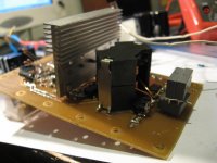
The top side
Also, I made a OV, UV and OC protections onboard. OV and UV I just stealed from iraudamp application note, and the OCP is from Philips UcD demonstration board application note. The problem is that I just had to NI those 3 outputs and send them to HIP, bit instead "NI" I made "I" gate and the HIP4081 was disabled all the time. So I just bypassed the protections and everything works now.
Also, I found the lower mosfets source return leads are connected wrong (not totally wrong, 'cos it is working). I didn't connect the chips source return pins directly to mosfets, but to ground. And the lower mosfets legs aren't connected to common ground, but instead I have current sensing resistors between source and gnd so there is a voltage difference that gets bigger when bigger current flows through mosfets/speaker.
Ah, this UcD is so forgiving 🙂).
Attachments

Good work for the end of 2008.
I wouldn't try to optimize such a circuit without a scope, you have a lot of courage.
how will you optimize it?
I will have a look to this thread as the results seems encouraging for a so simple schematic.
Have fun!
I wouldn't try to optimize such a circuit without a scope, you have a lot of courage.
how will you optimize it?
I will have a look to this thread as the results seems encouraging for a so simple schematic.
Have fun!
Sure, I was just planning to write some update.
I turned out that my amp had some emi problems. On one TV channel I had a lot of interference when the amp was turned on. Bad 🙁. Playing with gate resistors and HIP's dead time settings did not improve this so I guessed it was layout problem.
So I decided to draw another board. It took a while because I don't have much spare time for my hobbies, but about a week ago, I finished new board.
I shifted mosfets as close as I could get to gate driver chip, placed source return leads under gate leads, managed to route the board so I can pick all 4 mosfets and 12V regulator with same heatsink which I took from some old computer supply. I also now have four 100nF capacitors bypassing the rails on each upper mosfet.
It was time to use some better mosfets, so I bought some FDP3682 at Farnell (only 18,5nC of gate charge in TO220 package).
The amp is happily switching at about 380kHz. The funny thing is that the first time I turned it on it started to switch at 1600MHz (at least that's what my multimeter showed), and the mosfets were getting pretty hot at idle and the speaker produced a lot of noise . Then I added some capacitance across comparator inputs and the frequency decreased to what I have now.
I set the dead time to 20ns on the HIP4081 and the gate resistors are 15ohms.
Now, I have no interference with TV, and the amp runs totally cool and quiet, I feel like it could run full power without heatsink.
Taking into account that this amp is made without scope, I'm pretty happy with the result.
I feel that the dead time could be made much smaller, but I don't want to play with it without the right measuring equipment, and it is working just fine the way it is now.
Last weekend it was my birthday, and I used this new amp to power my 12" Peerless XXLS sub (830844 with PR) on a party I organized for my friends.
It worked perfectly without any fault and I was pretty impressed by it's ability to control the speaker cone.
For supply I used one 200VA transformer I had from some old project and two Rubycon 10000uF/63V capacitors I bought in some local store for about 10euros. Voltage after rectifier is 60V. I found that this low power transformer is enough for full power with music because of the large amount of supply capacitance. The whole thing is made in a rush so I could use it for my party 😎 so I wonder how the amp worked at all 🙂
I'll try to upload some pictures tomorrow, now It's pretty late here.


I know the board look ugly because while I was tweaking it (dead time, gate resistors,...etc), I desoldered and soldered again some elements few times, and with smd everything gets ugly after some time. Also, OVP and UVP didn't work properly again (actually it did, but I messed up the logic of turning the amp and the indicator leds on and off  ) so again some soldering.
The output inductor is wound on Epcos RM14 core with N87 material. I made a gap of about 2mm in it by sanding the central piece with my proxxon drill. I know I could use smaller core, but I bought the core first time when idea of making a class D amp flied through my head and I didn't know nothing about it. 🙄
) so again some soldering.The output inductor is wound on Epcos RM14 core with N87 material. I made a gap of about 2mm in it by sanding the central piece with my proxxon drill. I know I could use smaller core, but I bought the core first time when idea of making a class D amp flied through my head and I didn't know nothing about it. 🙄
hehe, yes, that's what counts 🙂
Now, it would be nice to make SMPS to power that thing. I just accidentally have one more core and few lowESR 2200uF/100V Epcos electrolytes 🙂.
..just need to find some proven design, I just don't have the time to get into the theory again.
Now, it would be nice to make SMPS to power that thing. I just accidentally have one more core and few lowESR 2200uF/100V Epcos electrolytes 🙂.
..just need to find some proven design, I just don't have the time to get into the theory again.
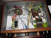
This is how it is impemented for now
I had one case from some old amp and I just throwed everything in it. on the left is the transformer and the PS board, and on the right, the amp board and the subwoofer crossover (stereo to mono, 24db LR variable lowpass, phase adjust, volume, rumble filter and balanced out for driving bridged amp like this).
It is funny that this almost half kW amp is the smallest thing af all components in that box and produces the least heat 🙂 😎
The next thing is to make some decent box to put all that into, because now it just waits for an accident wired like this
Attachments
- Status
- Not open for further replies.
- Home
- Amplifiers
- Class D
- Single supply bridge UcD, referencing the signals