

Stereo Tokin SIT Mu Follower Follower in 4U 400mm Chassis & 44VDC Power Supply
Although I have tried to maximize the power output of this circuit while trying to keep the power supply and heat dissipation within reason, there are diyers who would like to build something that is more accessible.
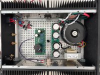
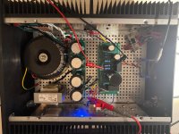
Since many have built First Watt amplifiers utilizing 2X18VAC power transformers and 4U 400mm chassis, I have modified the circuit to operate at 44VDC and 2A. With a heat dissipation of 88W per channel, this would fit nicely in the 4U 400mm chassis with one channel per side for a stereo setup, and the 2x18VAC transformer power supply with the 18VAC secondaries in series will net 44 to 45VDC. I recommend a minimum of 400VA for the transformer.
LTSpice simulations estimated the 8 Ohm power output at 1% THD to be about 22W, with the second harmonic still dominant.
The existing amplifier PCBs may be used for this circuit. The following schematic shows the component changes to suit this circuit. With the lower voltage and current, the P channel mosfet may be changed to an IRFP9240, and electrolytic capacitors may be 50VDC rated.
I recommend a CLC power supply filter to keep the amplifier noise level low.

22W @ 8 Ohm:


1W @ * Ohm:


Although I have tried to maximize the power output of this circuit while trying to keep the power supply and heat dissipation within reason, there are diyers who would like to build something that is more accessible.
Since many have built First Watt amplifiers utilizing 2X18VAC power transformers and 4U 400mm chassis, I have modified the circuit to operate at 44VDC and 2A. With a heat dissipation of 88W per channel, this would fit nicely in the 4U 400mm chassis with one channel per side for a stereo setup, and the 2x18VAC transformer power supply with the 18VAC secondaries in series will net 44 to 45VDC. I recommend a minimum of 400VA for the transformer.
LTSpice simulations estimated the 8 Ohm power output at 1% THD to be about 22W, with the second harmonic still dominant.
The existing amplifier PCBs may be used for this circuit. The following schematic shows the component changes to suit this circuit. With the lower voltage and current, the P channel mosfet may be changed to an IRFP9240, and electrolytic capacitors may be 50VDC rated.
I recommend a CLC power supply filter to keep the amplifier noise level low.
22W @ 8 Ohm:
1W @ * Ohm:
The estimated output power of 22 W at 8R and 1% distortion corresponds well to reality.
This can even be achieved with lower bias at about 1.4 A and a dual power supply +/- 23.5 V (s. post #711)🙂
This can even be achieved with lower bias at about 1.4 A and a dual power supply +/- 23.5 V (s. post #711)🙂
2A will result in a much higher 4 Ohm power output than 1.4A though. Simulation showed about 18W for 44VDC 2A into 4 Ohm. Real life result would probable be close to the simulation.
The beauty of diy is that the builder can choose what they want from their build. 🤓
44VDC 2A at 4R LTSpice simulation:


The beauty of diy is that the builder can choose what they want from their build. 🤓
44VDC 2A at 4R LTSpice simulation:
Yes, it can be done. With a 36VDC power supply at 1.5A and some resistor changes, it should output about 9W into 8 Ohm or 4 Ohm.
I was just curious what people use for a Chassis input fuse. My targets are 62V and 3A. The IXTN40P60P AND THF-51S are pretty rugged but I don't know what the the headroom should be or limiting factors are practically for the rest of the circuit. Or, is it really a thermal limiting problem. Trying not to guess. Thanks,
Don
Don
The fuse is usually determined by the power transformer VA rating as the fuse has to survive the power-up inrush current. I usually determine fuse value by this:
Slow Blow Fuse value = (transformer VA)/(AC line voltage)
Slow Blow Fuse value = (transformer VA)/(AC line voltage)
If the CL60 is for power supply ground lift, it should be connected at the power supply output. Since the amp requires a V- power supply, V+ at the power supply board is Ground. So connect the ground lift CL60 to the PS board output V+. You have a choice of connecting the CL60 at the AC safety ground with a wire between the CL60 and the PS board, or connecting the CL60 at the PS board and a wire between the CL60 and AC safety ground.
From an electrical point of view, the capacitor is not too close to the THF-51S. The important thing is to keep the interior of the amp and the capacitors as cool as possible. That requires good flow of air into and out of the interior of the chassis. So ventilation holes/slots are required in the chassis floor for the air to enter and in the chassis top/lid for the air to exit.. The chassis also needs feet high enough to allow good air flow below the chassis floor.
From an electrical point of view, the capacitor is not too close to the THF-51S. The important thing is to keep the interior of the amp and the capacitors as cool as possible. That requires good flow of air into and out of the interior of the chassis. So ventilation holes/slots are required in the chassis floor for the air to enter and in the chassis top/lid for the air to exit.. The chassis also needs feet high enough to allow good air flow below the chassis floor.
No P1. I have the original board.
I am running my TDA1541A dac directly into the preamp with only an I/V resistor so the dac output voltage is only about 0.15V max.
The subsequent output signal from the DIY FE 2022 is just barely enough. Right now I have my Sony 2SK79 preamp back in the system. It has higher gain and higher maximum output voltage.
Looking good!
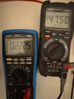
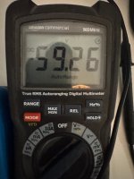
Vds at 47.5V is high though if the power supply is 59V. I suggest Vds at half of power supply voltage.
Have you tested it with speaker and music? You can use a preamp that has gain to test.
.
Vds at 47.5V is high though if the power supply is 59V. I suggest Vds at half of power supply voltage.
Have you tested it with speaker and music? You can use a preamp that has gain to test.
.
I just powered it up with the pots turned anticlockwise (as per your power-up manual, which is great btw) and took measurements. That’s all.
So Vds around 29V.
What would be an impact if I keep bias low, let’s say at 2.2A? I do not need a lot of power (my horns are 107dB with active subs)
Work will continue next weekend.
So Vds around 29V.
What would be an impact if I keep bias low, let’s say at 2.2A? I do not need a lot of power (my horns are 107dB with active subs)
Work will continue next weekend.
- Home
- Amplifiers
- Pass Labs
- Single Ended Tokin SIT THF-51S Common Drain Mu Follower Amplifier, 45W?