
would you please share the LTspice file?Thanks for the model an the comments. The IXTN40P50P model provicdd by IXYS seem to be broken or at least not compatible with LTSpice.
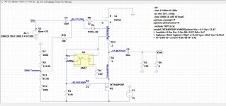
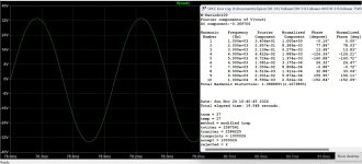
I managed to modify the schematic for +/- 33V rails and about 3A of quiescent current.
Simulation results look promising so far. Dissipation of is approx. 100W per device, as expected. Still need to check SOAs.
IXTN40P50P vs. IXTK40P50P: RthCS of the latter three times as high. Nevertheless, 0.5K/W heatsink should be sufficient.
View attachment 1357600
My amps are forced air cooled and the heat sinks are only warm when they reach temperature equilibrium. The THF-51S are definitely not pushed to their limit. So for something to do, I have been playing with LTSpice to see what might happen with higher power supply voltages.
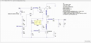
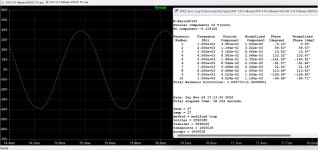
My amps have 80V capacitors in their power supply so I tried 75V and 3.0A. The simulations indicated that 70W to 75W at 8 Ohm is possible. The THF-51S dissipation would be about 110W, well within its 400W maximum with temperature taken into consideration.
I do not want to spend the money for higher voltage capacitors, but I also tried 90V and 3.0A and the simulations indicated that 90W to 100W at 8 Ohm is possible. Dissipation would be about 130W, again still reasonable with proper cooling.
By the way total dissipation per channel would be double since the mosfet will also dissipate approximately the same amount of energy. Since this is a winter amplifier for me, providing music and heat to augment the electric heating in my room, the additional electricity spent on powering the amps is saved by using less electricity to power electric baseboards.
So I plan on going ahead and upping the power supply voltage to 75V. Presently the power supply voltage is around 63V and at 3.0A, the amplifier is good for 50W at 8 Ohm. That is more than enough for my system but this is diy and a hobby. I am doing this not because I need the power but because I want to, for the fun of doing it. But then I don't need a fast car either. It would be great fun to go for the higher power supply voltage and try for 100W output, but I am too cheap to redo the power supply with 100W capacitors.
I intend to start by just increasing the power supply voltage to the existing amplifier. Hopefully that will go smoothly and produce the power output that LTSpice predicted. I do not expect the the LTSpice distortion numbers to be accurate. The real life numbers will most likely be higher.
Part two will be a modified circuit with a buffer at the input, with THF-51S bias voltage applied at the buffer gate a la Zen Mod.
Attachments
At Burning Amp this year, Bob Flocchini ( @flocchini ) gave me a great deal on two Antek AN-5230 transformers. They are 500VA dual 30V secondary transformers - perfect for a 75V power supply. Thank you, Bob.
So I Quasimodoed them with the two 30V secondaries in series. To make the snubber component connections neater I fired up KiCad and made a pcb to fit onto the bridge rectifier. And the price for five pieces from JLCPCB was US $3.52 with the slowest shipping option - can't beat that price.


So I Quasimodoed them with the two 30V secondaries in series. To make the snubber component connections neater I fired up KiCad and made a pcb to fit onto the bridge rectifier. And the price for five pieces from JLCPCB was US $3.52 with the slowest shipping option - can't beat that price.
I am afraid to ask, where do the other 15v come from? I have yet to figure out how that works. To me is PFM… pure freaking magic.
I am afraid to ask, where do the other 15v come from? I have yet to figure out how that works. To me is PFM… pure freaking magic.
Rectifying 60VACrms to fully filtered VDC : VDC = 1.414 x VACrms
However there are losses associated with the rectifiers, transformer, and power supply filtering, so typically the final power supply output VDC is approximately 1.25 x VAC of transformer secondary voltage.
Looking good. 🙂
If this one works out good, im thinking this is a perfect candidate for building a true point to point build of your circuit. As a different flavour build, to my current Singing bush and Lazy singing builds.
The future looks very fine, this could be really fun!
🎺🙂🎸
If this one works out good, im thinking this is a perfect candidate for building a true point to point build of your circuit. As a different flavour build, to my current Singing bush and Lazy singing builds.
The future looks very fine, this could be really fun!
🎺🙂🎸
My intuition tells me that you already have this completed and are currently trying to tamp down any bias that would cloud your opinions of the upgrade while listening (and heating the house) ..ha ha!
Always fun to see your work...Take care.
Always fun to see your work...Take care.
Just joking Ben.... Anxious to see your progress. Still love my amps..Thanks for all your hard work making them happen.
Ben, are you still providing Gerbers? I am finally getting back to building want to build this. Thanks in advance.
Yes, files sent. I have included the 80V PS board and the snubber board (post #725) in case you want those too.
Hi,
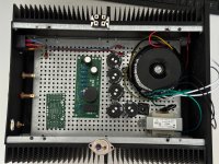
@Ben, thank you again for the Gerber files and this project. As discussed, I share few pictures in the thread.
Build:
My initial idea was to use the same PSU for Front End 2022 (0-60V).
At this moment I am considering to use 2x 22V secondaries for powering up the Front End. I would regulate it to 2x 24V DC – input signal is balanced.
Any suggestions to the PSUs and components placement?
Cheers
Jacek
@Ben, thank you again for the Gerber files and this project. As discussed, I share few pictures in the thread.
Build:
- 2x 3U 400mm chassis
- trafo has 3 secondary wingdings: 1x 49V, 2x 22V
- PSU: 2x 17000uF - 159ZG 15mH – 3x 170000uF
My initial idea was to use the same PSU for Front End 2022 (0-60V).
At this moment I am considering to use 2x 22V secondaries for powering up the Front End. I would regulate it to 2x 24V DC – input signal is balanced.
Any suggestions to the PSUs and components placement?
Cheers
Jacek
Attachments
Hi Jacek,
I like the idea of using the amplifier power supply to power the Front End. Even though amplifier power supply is not regulated, it will probably be quiet enough with the CLC filter. Note there are First Watt amplifiers with front ends powered by the amplifier's power supply. But the main reason why I like the idea is that the Front End will be provided with enough voltage or close to enough voltage to be able to drive the amplifier section to its maximum output. With a 24V bipolar or 48V unipolar supply, that would not be possible. I run my DIY FE at 62V, and Nelson mentioned in his DIY FE2022 article that he had tested the J113 and KSA992 to 70V maximum.
Your component layout looks feasible. I suggest placing the bridge rectifier on the right side of the chassis, the input to the capacitor bank on the right side of the chassis, and the output of the capacitor bank on the left side of the chassis.
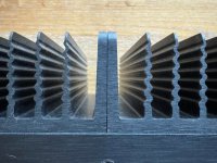
Your heat sinks are in two pieces per side so they need to be connected with a piece of aluminum to be able to spread the heat from the centrally mounted SIT or Mosfet. I suggest a minimum thickness of 6mm, full height, and length to cover at least one third of each piece of heat sink.
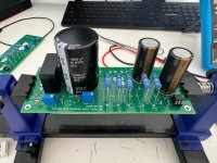
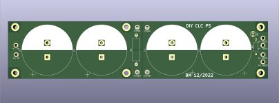
I see that you will be using power supply electrolytic capacitors with two leads. I have a CLC power supply PCB design that is sized for 10mm lead spacing 35mm maximum diameter capacitors. It is laid out for four capacitors, not five capacitors though. I can send you the Gerber files if you want them.
I like the idea of using the amplifier power supply to power the Front End. Even though amplifier power supply is not regulated, it will probably be quiet enough with the CLC filter. Note there are First Watt amplifiers with front ends powered by the amplifier's power supply. But the main reason why I like the idea is that the Front End will be provided with enough voltage or close to enough voltage to be able to drive the amplifier section to its maximum output. With a 24V bipolar or 48V unipolar supply, that would not be possible. I run my DIY FE at 62V, and Nelson mentioned in his DIY FE2022 article that he had tested the J113 and KSA992 to 70V maximum.
Your component layout looks feasible. I suggest placing the bridge rectifier on the right side of the chassis, the input to the capacitor bank on the right side of the chassis, and the output of the capacitor bank on the left side of the chassis.
Your heat sinks are in two pieces per side so they need to be connected with a piece of aluminum to be able to spread the heat from the centrally mounted SIT or Mosfet. I suggest a minimum thickness of 6mm, full height, and length to cover at least one third of each piece of heat sink.
I see that you will be using power supply electrolytic capacitors with two leads. I have a CLC power supply PCB design that is sized for 10mm lead spacing 35mm maximum diameter capacitors. It is laid out for four capacitors, not five capacitors though. I can send you the Gerber files if you want them.
Attachments
It's Ben a while, but I have to chime in and say it's top notch.

Hi Ben,
Thank you very much for all the suggestions and PSU Gerber files offer, which I gladly accept.
I will go with the unregulated power supply for the Front-end.
Regarding the thermal bridge between the heat sinks. This is something I need to explore. I was thinking of just using thermal paste between them (picture) as the surface is very even and relatively large (48 sq. cm = 7.5 sq. inch). What do you think?
Jacek
Attachments
- Home
- Amplifiers
- Pass Labs
- Single Ended Tokin SIT THF-51S Common Drain Mu Follower Amplifier, 45W?