For my personal version I`ll be using 8 Ohm speakes and +45V DC power supply for higher power, next set of measurements, will be for that option.
Member
Joined 2009
Paid Member
On the bottom layer of my proto pcb, under the one electrolytic, you could see layout for 1206 10uF cap for bypass, is this a bad idea or not? These caps are cheap..
depends on the cap, usually you want to avoid piezoelectric ceramics (multi layer npo is good),
I like to have my boards clean after soldering, washing off the flux with acetone (regular lead solder).
Soon, schematic with edited, final values of components, and new measurements..
Hi Bogdan, Waiting for final schematic to make adjustments to the layout, if any.
regards
prasi
Prasi, ok, I'll send finall values leter, I hope there will be no changes in the schematic, maybe something minor about compensation I still have some experiments to try..
Thanks Bigun, yes I'll clean everything after experiments... And yes I've meant multilayer caps.
Thanks Bigun, yes I'll clean everything after experiments... And yes I've meant multilayer caps.
I ran into a similar circuit during speculations as to what was under the hood of a cheap Schitt headphone amp. The relevant circuit is shown in post #11 here:
What's in the box?
Perhaps more food for thought...
What's in the box?
Perhaps more food for thought...
Last edited:
I ran into a similar circuit during speculations as to what was under the hood of a cheap Schitt headphone amp. The relevant circuit is shown in post #11 here:
What's in the box?
Perhaps more food for thought...
Yes it`s similar, but push pull, I tought of current mirror also but kept it minimalistic as I could. Thanks for a hint.
Hi Prasi,
I know this layout doesn’t have much “extra” space, but if you could create a bit around C1 to allow a film cap to fit that would be great! 🙂
I know this layout doesn’t have much “extra” space, but if you could create a bit around C1 to allow a film cap to fit that would be great! 🙂
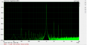
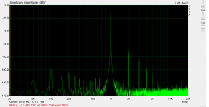
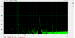
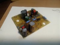
It's connected to speakers again. Sounds very good and there's a subtle but hearable difference in sound even at low levels under 1W. Sound with degeneration resistor and higher 2nd harmonic is more "sweet", while bypassed deg.resistor with lower second harmonic, sounds more "transparent" to me with better bass control.
Now the harder part, the chassis 😀
Btw, Prasi R22 is 100R.
Now the harder part, the chassis 😀
Btw, Prasi R22 is 100R.
Hi Vunce,
I already have film cap of 15mm pitch x 7.2mm wide...
can tell me part number that you have in mind?
I already have film cap of 15mm pitch x 7.2mm wide...
can tell me part number that you have in mind?
Hi Prasi,
Most of the axial lead 2.2uF PP film caps I use are a min. 20mm x 12mm in size.
Maybe add another set of pads spaced 20mm and the leads could be shaped to fit around the cap ends to fit in the 20mm LS. The width shouldn’t be a problem because the one side is free at the edge of the board, the other side has space until the trimpot is reached.
Thank you for considering the request.
Hi Borko,
The “damping factor” switch is a neat feature to incorporate, Cool!
This project could lend itself nicely to use CPU coolers/fan with a higher bias for a very compact amplifier module.
Cheers,
Vunce
Last edited:
Hi Prasi,
Hi Borko,
The “damping factor” switch is a neat feature to incorporate, Cool!
This project could lend itself nicely to use CPU coolers/fan with a higher bias for a very compact amplifier module.
Cheers,
Vunce
Thanks Vunce, I will also use (what I have at hand) smaller heatsinks with with 12cm fan on low rpm something like in Krell KSA 50.
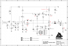
Hello Bogdan,
thank you for the updated schematic.
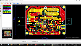
here is updated files and gerbers.
To Vunce,
now i have there 22.86mm pitch x 9mm cap. so plenty of options of either PP or polyester caps (15mm pitch and 10mm pitch too).
i have also copied some traces on top, so if someone wants to manufacture pcbs, they get nice masks and pads on both sides.
regards
Prasi
thank you for the updated schematic.
here is updated files and gerbers.
To Vunce,
now i have there 22.86mm pitch x 9mm cap. so plenty of options of either PP or polyester caps (15mm pitch and 10mm pitch too).
i have also copied some traces on top, so if someone wants to manufacture pcbs, they get nice masks and pads on both sides.
regards
Prasi
Attachments

Last edited:

When I was doing single sided boards with power transistors on the bottom side, I found it useful to use eyelets on the power device leads so that I could adjust the device spacing, and then solder the power devices in place from the top side. It saves some headaches. Also, many manufacturers use eylets for snap-in and other large caps so you get extra retention from the solder fillet.
Great Prasi thanks a lot! R15 is also 2W resistor.
I'm assembling another channel to hear it finally in stereo 🙂.
It's a slow, but enjoyable process..
Thanks Bogdan,
Yes a 2w can be fit there , so also BPR 56 type 5W also for R16/R17.
To Vunce,
The Gerbers posted earlier had some silk screen issues (part values were also included creating text overlap). here are correct gerbers. Also posting other files for convenience.
Attachments
-
GERBERS-CAP BANK_2020-07-07.zip114.9 KB · Views: 90
-
gerbers-SECFA-V4_2020-07-06.zip318.8 KB · Views: 86
-
CAP BANK-SILK AND CU-BTM-MIRRORED.pdf416.4 KB · Views: 118
-
SE CFA-CU-BTM-MIRRORED.pdf437 KB · Views: 134
-
SE CFA-SILK-MIRRORED.pdf474.9 KB · Views: 121
-
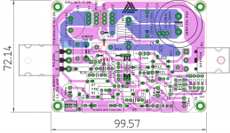
 picture.png128.1 KB · Views: 309
 -
 SECFA-LAY-v4.png92.6 KB · Views: 298
 -
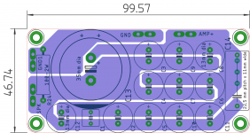 cap bank.png50.8 KB · Views: 183
 -
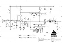 SECFA-SCH-v4.png23.3 KB · Views: 548
Last edited:
When I was doing single sided boards with power transistors on the bottom side, I found it useful to use eyelets on the power device leads so that I could adjust the device spacing, and then solder the power devices in place from the top side. It saves some headaches. Also, many manufacturers use eylets for snap-in and other large caps so you get extra retention from the solder fillet.
Thanks wrenchone, practical idea, what kind of eyelets, never seen it on a pcb, any photos?
- Home
- Amplifiers
- Solid State
- Single Ended CFA