You might want to remove the emitter resistors during further testing. This will cut off the outputs.
This is a VERY bad idea. The driver transistors will run full on into the 100 ohm resistor, because the Allison transistors will be off.
- keantoken
It seems that most people think those emitter resistors are just like in any AB amplifier, not realizing that they are 1/2 of the entire circuit's purpose. The Allison must be really odd...
- keantoken
- keantoken
True enough Kean, I wasn't thinking.
I just came back to the computer to ask about this... I had not idea.
well, I cooked something, the 100 ohm resistor keeps smoking. Thought it was the A1837, which is pain to get to have to remove the output tranistor to replace it, but, nooo it wasn't that one. Still looking, hopefull I will solve this and get back to actual testing tomorrow.
Ken
Ken
Did you remove Re1 and Re2 on MJL's advice? This was actually a mistake on his part.
If not, check to see that Q8 and Q9 are working. If the outputs stop working, Q8 and Q9 won't turn on as well, causing Q1 and Q5 to smoke the 100 ohm resistor...
- keantoken
If not, check to see that Q8 and Q9 are working. If the outputs stop working, Q8 and Q9 won't turn on as well, causing Q1 and Q5 to smoke the 100 ohm resistor...
- keantoken
Ken,
Your Allison biased output is almost certainly oscillating. There are two feedback loops involved, each consisting of the Allison bias transistor, the driver transistor and the output transistor. These three transistors have some phase shift at high frequency, eventually this turns the loop from negative feedback to positive feedback, and hence it oscillates. The loop gain needs to be reduced to less than 1 before the oscillation frequency.
Build just the output stage (no 49811) and get it stable first. Use large emitter resistors (start at 10ohm, then 1ohm, then 0.33ohm), and a large load (start at 100ohm, then 10ohm, then 4ohms). This will keep the currents small until you get it stable.
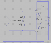
See the attached diagram, and note the following:
- Small resistors in the bases of the output and driver transistors (100 and 4.7 are reasonable values). Put these close to the bases.
- Frequency compensation networks of Ra1/C1 and Ra2/C2. Values of 560/100pF should be a good starting point, but you may be able to get down to 22pF.
- C1 doesn't do much, but it helps with square waves. While this doesn't matter for music, testing with square waves can be very informative, so put it in. Any value from 1nF to 100nF should be OK
- The current sources can be suitable value resistors to give about 5mA. These eventually get replaced by the LME49811 source/sink current sources.
Test by driving it with a voltage source between the Q5,Q6 emitters at about 1 volt. There should be a small gain rise around the 1MHz range, but only a few dB. Also try mixing a square wave and a much higher frequency sine wave to see if it unstable. Eventually test with 4ohm paralleled with 1uF. Try just letting it sit with no input, if it gets hot, it will be due to oscillations.
If you absolutely cannot get it stable, then change to lower Ft output transistors, such as the mjl21193/mjl21194 type. Once you have the output stage working, then you can try with the LME49811 driver.
Note that the Allison bias scheme is for `Sliding Class A Bias'. It doesn't work as a Class A/B output stage! Actually it does work, just very badly, with lots of distortion.
I hope this helps, and good luck.
Paul Bysouth, Nov 2009
Your Allison biased output is almost certainly oscillating. There are two feedback loops involved, each consisting of the Allison bias transistor, the driver transistor and the output transistor. These three transistors have some phase shift at high frequency, eventually this turns the loop from negative feedback to positive feedback, and hence it oscillates. The loop gain needs to be reduced to less than 1 before the oscillation frequency.
Build just the output stage (no 49811) and get it stable first. Use large emitter resistors (start at 10ohm, then 1ohm, then 0.33ohm), and a large load (start at 100ohm, then 10ohm, then 4ohms). This will keep the currents small until you get it stable.
See the attached diagram, and note the following:
- Small resistors in the bases of the output and driver transistors (100 and 4.7 are reasonable values). Put these close to the bases.
- Frequency compensation networks of Ra1/C1 and Ra2/C2. Values of 560/100pF should be a good starting point, but you may be able to get down to 22pF.
- C1 doesn't do much, but it helps with square waves. While this doesn't matter for music, testing with square waves can be very informative, so put it in. Any value from 1nF to 100nF should be OK
- The current sources can be suitable value resistors to give about 5mA. These eventually get replaced by the LME49811 source/sink current sources.
Test by driving it with a voltage source between the Q5,Q6 emitters at about 1 volt. There should be a small gain rise around the 1MHz range, but only a few dB. Also try mixing a square wave and a much higher frequency sine wave to see if it unstable. Eventually test with 4ohm paralleled with 1uF. Try just letting it sit with no input, if it gets hot, it will be due to oscillations.
If you absolutely cannot get it stable, then change to lower Ft output transistors, such as the mjl21193/mjl21194 type. Once you have the output stage working, then you can try with the LME49811 driver.
Note that the Allison bias scheme is for `Sliding Class A Bias'. It doesn't work as a Class A/B output stage! Actually it does work, just very badly, with lots of distortion.
I hope this helps, and good luck.
Paul Bysouth, Nov 2009
Attachments
Thanks Paul, I've forgotten completely about that compensation and forgot to mention it to Klewis... It's the one that works the best (I believe, but there is one other way that does not affect THD20 and as you know I'm a perfectionist to a flaw).
I am incredibly biased against Ra1 and Ra2. To me it's comical, I've tried every possible other compensation scheme and there's only one I think that compares (but it hasn't been tested in real life).
Paul's method is guaranteed to work, and chances are you won't hear the difference between that method and mine. I developed mine for probe applications where HF THD was an issue, but at these frequencies I don't know if there is an audible difference (not to mention that the 49811 will be correcting any errors).
- keantoken
Ken,
Your Allison biased output is almost certainly oscillating. There are two feedback loops involved, each consisting of the Allison bias transistor, the driver transistor and the output transistor. These three transistors have some phase shift at high frequency, eventually this turns the loop from negative feedback to positive feedback, and hence it oscillates. The loop gain needs to be reduced to less than 1 before the oscillation frequency.
Build just the output stage (no 49811) and get it stable first. Use large emitter resistors (start at 10ohm, then 1ohm, then 0.33ohm), and a large load (start at 100ohm, then 10ohm, then 4ohms). This will keep the currents small until you get it stable.
See the attached diagram, and note the following:
- Small resistors in the bases of the output and driver transistors (100 and 4.7 are reasonable values). Put these close to the bases.
- Frequency compensation networks of Ra1/C1 and Ra2/C2. Values of 560/100pF should be a good starting point, but you may be able to get down to 22pF.
- C1 doesn't do much, but it helps with square waves. While this doesn't matter for music, testing with square waves can be very informative, so put it in. Any value from 1nF to 100nF should be OK
- The current sources can be suitable value resistors to give about 5mA. These eventually get replaced by the LME49811 source/sink current sources.
Test by driving it with a voltage source between the Q5,Q6 emitters at about 1 volt. There should be a small gain rise around the 1MHz range, but only a few dB. Also try mixing a square wave and a much higher frequency sine wave to see if it unstable. Eventually test with 4ohm paralleled with 1uF. Try just letting it sit with no input, if it gets hot, it will be due to oscillations.
If you absolutely cannot get it stable, then change to lower Ft output transistors, such as the mjl21193/mjl21194 type. Once you have the output stage working, then you can try with the LME49811 driver.
Note that the Allison bias scheme is for `Sliding Class A Bias'. It doesn't work as a Class A/B output stage! Actually it does work, just very badly, with lots of distortion.
I hope this helps, and good luck.
Paul Bysouth, Nov 2009
Paul and Keantoken,
After rebuilding the board by changing out all the transistors, I got back to a steady state of 11Mhz oscillations and 1.3v bais. I tried a 33pf bypass cap on Rf, it stopped the oscillation but made a kind of standing wave which made one of the drive transistors run hot. So, I removed the bypass cap and
implemented Paul's scheme.
I tried it with just the 100/4.7 combo first, but no go, still oscillating at 10Mhz. Used || 10 ohm in lieu of 4.7 ohm. and 511 ohm instead of 560, but otherwise had the parts on hand. Then added 511 ohm in lieu of 560(what I had on hand) and 100pf mica caps. It runs. I just modified the existing boards and gave it a run with the LME49811 - I'm pretty convinced that I haven't blown one of the LME49811's yet. The sine wave is not perfectly smooth across the top and bottom, very slight hint of noise. The oscillations are gone. Ran 1k hz, 10k hz and 100k hz square wave, all were fine, no appreciable overshoot, the 100k hz was rounded over on the leading edge. All of these had a .15v ptp input. When I reduced the input voltage on the 1k hz input to approx .01v the top of the square wave had small up/down excersions.
Tested it with music, sound was clear and crisp, maybe a bit bright, though maybe just my imagination.
Thoughts on other things to do or test that might smooth out the sinewave a bit more?
Thanks for all your help.
Ken
The Allison has an odd problem where if you don't get it completely stable, it will oscillate, but chaotically and not a true oscillation. This may be the noise you're noticing.
Try this: connect one probe to the output and the other to the collector of the 2SC3503. You should see nothing but a normal wave. Look for chaotic, spikey looking noise.
The Allison is more prone to oscillation at power peaks, so you may need to increase the compensation.
I don't see why there would be any visible noise on an oscilloscope unless there was something wrong.
EDIT:
Okay, this should tell us for sure if the Allison is oscillating, but more importantly whether the LME49811 is driving it properly. If you can, add the 10 ohm resistor below, probe the voltage across it and describe the trace. (This resistor can also improve stability, though I haven't looked into its affect)
- keantoken
Attachments
Last edited:
Paul:
I don't know the standard methods used to do this, so I want to ask someone who has the knowledge. To all my knowledge, this compensation method works good enough without affecting THD20. Based on simulation, I believe this method can be used in place of the standard method. Can you confirm this?
C1 is the main compensation capacitor.
Thanks,
- keantoken
Attachments
keantoken,The Allison has an odd problem where if you don't get it completely stable, it will oscillate, but chaotically and not a true oscillation. This may be the noise you're noticing.
Try this: connect one probe to the output and the other to the collector of the 2SC3503. You should see nothing but a normal wave. Look for chaotic, spikey looking noise.
The Allison is more prone to oscillation at power peaks, so you may need to increase the compensation.
I don't see why there would be any visible noise on an oscilloscope unless there was something wrong.
EDIT:
Okay, this should tell us for sure if the Allison is oscillating, but more importantly whether the LME49811 is driving it properly. If you can, add the 10 ohm resistor below, probe the voltage across it and describe the trace. (This resistor can also improve stability, though I haven't looked into its affect)
- keantoken
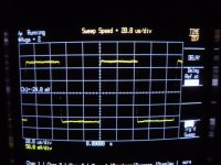
I added the resistor, put the probe on one side and the probe ground on the other. It produced a fuzzy line at at 5mv / 100ns scale. The line was moving up and down a bit, though not very far. I took a picture and will upload it tomorrow.
The resistor didn't seem to have a visible effect on the smoothness of the sine wave. I also took pictures of the "noise" in the low level square wave.
Ken
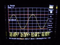
So, here are the photo's
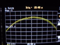
First one regular sine wave, you can see the top is not quite smooth.
Second one is the enlarged view of the same sine wave.
Sorry for the shaky hand, I turn the lights off and put tape over the flash to avoid reflections on the screen.
Ken
First one regular sine wave, you can see the top is not quite smooth.
Second one is the enlarged view of the same sine wave.
Sorry for the shaky hand, I turn the lights off and put tape over the flash to avoid reflections on the screen.
Ken
Attachments
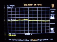
A few more pics.
The low voltage square wave showing a less than flat top and the noise measured of the 10 ohm resistor that connects the emitters of the Allison pair. Again sorry for the fuz.
A few other points, the Allison pair are not Keantoken's prefered devices, those should arrive this week, we will see if they make a difference. The output resistors are still at .22 and wirewound. I've ordered .3 3w metal film to see if that makes a difference. Does the type of compensation cap effect performance or sound quality? Currently they are mica caps.
Ken
Note that the Allison bias scheme is for `Sliding Class A Bias'. It doesn't work as a Class A/B output stage! Actually it does work, just very badly, with lots of distortion.
True, you can't get smooth AB crossing between error correctors that
suddenly cutoff at some threshold they absolutely can no longer correct.
The corrections only work well if neither device ever turns off or gets
pushed into clipping. Completely contrary to good AB design...
However, adding two Schottkys is all thats required to give shape to
a near perfect AB crossing. Very nicely, and with darn little distortion.
Still takes more than a pair of Schottkys to fix the ugly clipping issue.
This circuit sometimes tries way too hard to fix the unfixable glitches.
Last edited:
True, you can't get smooth AB crossing between error correctors that
suddenly cutoff at some threshold they absolutely can no longer correct.
However, adding two Schottkys is all thats required to give shape to
a near perfect AB crossing. Very nicely, and with darn little distortion.
Is there schematic to share? I'm will to build...
Ken
Is there schematic to share? I'm willing to build...
Ken
I'm trying to save letter, impending world shortage😉
Examples: PBSouth - Post#22 this thread. Mine - Post#68 this thread...
Same thing only different. Mine evolved from Aleph rather than Allison,
I wasn't aware at that time of Allison, nor Paul's prior use of the same
AB trickery.
If you visit "Possible Improvements for Aleph?" (in the Pass section),
you see where I stumbled upon Schottkys. Paul still beat me to it.
Now, here's one of my screwier ideas for entertainment value only!!!
Optos here prolly ain't fast enough to actually pull this stunt off.
But its got diodes in the output, the way you were asking about.
Either circuit drawing referenced above would work much better.
Attachments
Last edited:
- Home
- Amplifiers
- Solid State
- Simulation Analysis of several unique Allison-based output stages.