What are those numbers? mV across 100Ω drain resistor while g&s pins are connected together? What was the test voltage? 9-10V or 15V as in its datasheet?
Put the 536 554 in J3 positions, the 605 757 in J2 postilions, the 890 1020 in J1 positions. If you have, use 560Ω R4 to bring their Id comparable to the others so they get to dissipate less. They would have worked even if randomly positioned, but since you asked.I got only six pf5102. Measured the Idss, but they seem quiet different;
536
554
605
757
890
1020
Is this fine to use for the regulator? Or do i have to order some additional?
They would have shown bit more Idss each if tested at 15V datasheet nominal but their most current is already there at 10V test also. Trends as which one is stronger or weaker would not change.Ah sorry, correct indeed, mv across 100ohm with gs connected. Measured at 10v test voltage.
First time im matching transistors, so i thought lets try these before i start matching the 2sk170.Put the 536 554 in J3 positions, the 605 757 in J2 postilions, the 890 1020 in J1 positions. If you have, use 560Ω R4 to bring their Id comparable to the others so they get to dissipate less. They would have worked even if randomly positioned, but since you asked.
Measured again at 15v but all values get raised by 9-10mv
Will follow your advice on the positions.
I have to see if i have the resistor value laying around.
Thanks again Salas

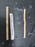
Found some 536ohm 250mw resistors, will 250mw be enough?
Else i got 464ohm 600mw.
These are weird values, its all in a small box i inherited from my uncle. All new resistors but just a lot of weird values you dont see often.
Else i got 464ohm 600mw.
These are weird values, its all in a small box i inherited from my uncle. All new resistors but just a lot of weird values you dont see often.
250mW is fine. We are dealing with very small currents there. The weird values must be coming from E48 or higher series.
250mW is fine. We are dealing with very small currents there. The weird values must be coming from E48 or higher series.
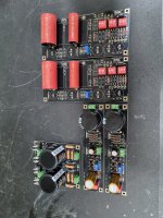
Attachments
I want to start matching the 2SK170BL's. Just a quick question on how to take the right measurement.
When i start the measurement the mA's raise quickly. Then they get to a point where the mA raises slower (around 2 seconds or so).
What is the correct value?
For the matching parts it isnt a problem as long as you measure every Jfet the same. But for selecting the mA's it is the questions what value needs to be taken into acount. In the BOM for instance it says that Q4 has to be between 8,3 and 8,5mA.
Maybe this questions has been answered somewhere in this topic, but i couldnt find is with the search function.
Avoid touching them, fingers will affect their case temperature, use a handling tool for the IDSS test. Let them settle for half a minute after applying voltage. They are characteristically positive in temperature coefficient those types at zero VDS and the 2SK369s are even worse for that. Do all samples on same day with same ambient temperature.
We want to know what Id bias will happen in the UFSP circuit so we want them warmed up matched not just matched. Other circuits can be using them at far less Id with much higher source resistor values. In such cases measuring them fast not to get perplexed by drift, not keep time, and done with it all quicker, seems a valid approach.
I am at an impasse. I have bought two 30VA toroidal transformers with a single 32VAC secondary and 230VAC primary. However, both toroids read 37 VAC when the primary is connected to a variac set on 230VAC. When I connect one toroid to my built (toroid -> RAW PSU -> UBiB -> FSP) I need to keep the variac at 200-205 VAC to be able to see 32VAC at the secondary, that corresponds to 40VDC at the UBiB. No problem here playing with both VR1 to get the 4VDC at the TP. If I bring the variac to 230VAC, the secondary reads 36VAC and 47VDC at the UBiB input. I did not play with the VR1s to see if I can regulate voltages because something seems to be off.
I suspect that the toroidals secondary are not 32VAC but 36VAC (they are made to order). The producer says that is normal to see higher voltage without load. Hower, I feel it is too much off.
Am I correct insisting with the producer to take them back for a check or am I missing something here?
I suspect that the toroidals secondary are not 32VAC but 36VAC (they are made to order). The producer says that is normal to see higher voltage without load. Hower, I feel it is too much off.
Am I correct insisting with the producer to take them back for a check or am I missing something here?
Hi, we have Rd/Link positions in the Raw PSU board where you can put 20R 2W-5W resistors to drop enough voltage when the raw DC output is loaded. Its precarious to exceed 45VDC input to the Ubib. If it won't adjust regulated output as expected anymore, then something got hit most probably J1.
Transformers output VAC spec is usually stated at their full rated current. Thing with small ones is they lose a lot of voltage between lightly and fully loaded. Thinner windings more impedance more loss. 100mA constant current demand per channel in this application is a rather light enough loading. Those you got are on the high side but manageable with Rd/link.
Transformers output VAC spec is usually stated at their full rated current. Thing with small ones is they lose a lot of voltage between lightly and fully loaded. Thinner windings more impedance more loss. 100mA constant current demand per channel in this application is a rather light enough loading. Those you got are on the high side but manageable with Rd/link.
I got the time to test with two 15R resistors I had on hands. With 15R in Rd/Link position I get 42V at UBiB input. With 30R it drops to 38V. I guess I will order the 20R suggested and should be spot on.
Both UBiB regulates fine (with either values above at the input) but I need to keep the output at 29V to be able to have 4V at TP. I can get away with 29.5V but not 30V.
Both UBiB regulates fine (with either values above at the input) but I need to keep the output at 29V to be able to have 4V at TP. I can get away with 29.5V but not 30V.
42V Bib input with 15R RD/Link is also good enough keeping if to avoid ordering spot on voltage drop 20R resistors.
TP 4V usually wants the lowest regulated voltage rail adjustment in MM mode asking for more each time you step up a sensitivity mode.
TP 4V usually wants the lowest regulated voltage rail adjustment in MM mode asking for more each time you step up a sensitivity mode.
- Home
- Source & Line
- Analogue Source
- Simplistic NJFET RIAA