
The higher the sensitivity setting the more the 2SK369s thermal drift you will see. By the time you are in LMC 61-62dB configuration you just want TP to wander in the ballpark. Nonetheless the AC signal in the input stage is much lower for MC/LMC so it rides the DC bias drift enjoying a relatively wider road than MM/HMC before its peaks have a chance to hit the guardrails so to speak.
Dear Salas,
Too many pages to read 😢.
Did you notice the dynamic output resistance of your folded cascode.
"Pfarrell" loves your design 🙂.
And I'm (a bit) afraid you (could) overlooked the so-called internal resistance when defining the passiv Network.
Sorry for that question, and apologies in advance - as i see' you did overlook it.
Best regards,
HBt.
Last edited:
@hbtaudio
You’re going to come to this thread and argue about phono stage design?
Please keep it polite and civil.
You’re going to come to this thread and argue about phono stage design?
Please keep it polite and civil.
Very friendly, soft and kind (political correct) '6L6'. My advice is: just don't speculate about my intentions!
Last edited:
Thank you Salas.
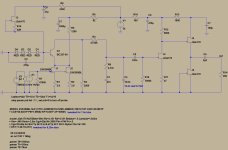
Then, in theory and simulation also, the network must be:
R1 = 44,8kOhm (just 43k + 1k8)
R2 = 6,5145kOhm (just 4k7 + 1k8 + 15)
C1 = 49nF (just 47n || 1n || 1n)
C2 = 17nF (just 15nF || 1n || 1n)
With these Numbers, PSPICE confirm and acknowledge with modelling your circuit - that these are the correct Values. Reference is the |H(jOmega| - based on referencelevel at f_signal = 1kHz compared with.
The approximation is over the whole audio band (now) better then +/- 0,1% with your Design, and so far correct now.
It is not my desire to argue or fight.
I just noticed it 😢. Perhaps i am overlooking something, but i didn't.
With respect and regards,
HBt.
The input impedance is not constant, and not 47k +/- j0.
It is frequencydepend. You have to include your 2k2-Resistor in the equation, and calculate the rest with based on 47k+2k2 = 49,2kOhm. Alternative: subtract it from 47k and put in the difference.
Maybe i am totally wrong, please correct me. In my opinion, you should always set up a complex transfer function first. The source resistance of the cascode is always in series with ...
They do add together for frequency response calculations, correct. Both their sum regarding base resistance and the next stage's Miller regarding HF have been included in the modeling.
I see.
Is there any measurement about the complete frequency response (with put them all together), to compare the difference between calculation (,simulation) and the entire plot of ...
Thank you Salas, it is allways a pleasure to be gentle.
HBt.
Bye the way,
are you willing to share your models of the semiconductors (you use, choose) with us?
Ciss is 30pF, Crss is 6pF for the k170 ...
Last edited:
@hbtaudio when are you going to design an amp?
Not ment to argue, but with your knowledge and experience and observation this has to be one hell of an amp coming out i guess..🤔
Hoping to finish my Salas preamp soon. Just a last check of all the values on the populated board and then build it into its case.
Not ment to argue, but with your knowledge and experience and observation this has to be one hell of an amp coming out i guess..🤔
Hoping to finish my Salas preamp soon. Just a last check of all the values on the populated board and then build it into its case.
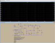
On my Motu M4 audio interface with C1 C2 C2Y caps chosen on my 2%+3 digits accuracy for 1kHz pf range DER EE LCR I measured it flat with 15nF+400pF=15.4nF C2,C2Y i.e. C4 on the SIM. Using software anti-Riaa filter curve in ARTA. The sim indicates 15nF+600pF=15.6nF with the specific models you can read in the attached pictures. People on real systems usually prefer it at 15.22-15.33nF nominal with 15nF 1% base cap and 2% pF tuning cap.I see.
Is there any measurement about the complete frequency response (with put them all together), to compare the difference between calculation (,simulation) and the entire plot of ...
Thank you Salas, it is allways a pleasure to be gentle.
HBt.
Bye the way,
are you willing to share your models of the semiconductors (you use, choose) with us?
Ciss is 30pF, Crss is 6pF for the k170 ...
Attachments
Now i think, i identify the underlying cause of the millions of misunderstandings - out there.
Thanks Salas,
HBt.
Thanks Salas,
HBt.
Dear Salas,
early in the snowy morning - I realize: You have not overlooked the output resistance (of the cascode) and the complex input resistance of the output stage.
In an approximate sense, I take from my simulation an input resistance of approximately: 400kOhm || 1.02nF. This is the load of our four-pole, passive RIAA network (simplified, but practical).
The theoretical values are therefore (without loading the complex voltage divider): R1=(2k2)+47kOhm; R2=7k154; C1=44n45; C2=15n26.
In an isolated consideration, we now subtract Ce(jOmega) from 15.26nF and consider Ce as a constant, ideal parallel capacitance. => C2=15.26nF (-1.02nF).
What do we now with the 400kOhm? The first thought is to increase R2 ... at the latest now' it gets complicated - trial and error!?
It is best to write a program that does the work for us, either approximating it or setting up a transfer function that matches reality (and solving it).
This is all a bit academic, sorry.
When I saw your circuit, the value of R2 (your R9) caught my eye and an automatic analysis started in my head.
I am always looking for the best possible approximation to the theoretical ideal.
Maybe I'm not really awake yet; there's nothing wrong with your circuit.
Even with possible deviations of +/- 0.5dB (1dB pp Span) you can live quite well. Often the resulting deviations are not that big and whether you can hear them depends on other factors.
Well done, I like your approach and "Pfarrell" loves it.
🙂
Is it snowing in Athens too?
☕
Best wishes,
HBt.
(Maybe I'll build one, but equalizers are starting to pile up in my house and my wife is getting angry 😉.)
Absolutely build it—only way to know if it works for you or not. Anger is oft tempered with good tunes...Just my observations...(Maybe I'll build one, but equalizers are starting to pile up in my house and my wife is getting angry 😉.)
Well done, I like your approach and "Pfarrell" loves it.
As do I. It is my favorite phono stage of all time, including the insanely expensive commercial products my friends own. If it is good enough for pfarrell, its good enough for me.
Well, it is my favorite phono too, and here - even if I am not in Athens, but pretty close - the sun is shining and went swimming in the sea today. 🙂Is it snowing in Athens too?
☕
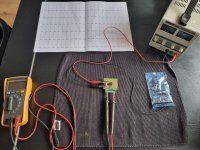
Ive tried measuring the leds today.. but with 9v and 1k5 (1k495) i measure Vf around 1.84-1.85v, so im not getting near 7.75v with 4 leds. I have to raise the voltage to at least 14v to see a dropping voltage of 1.9v
I have a lab supply connected. And measure the voltage with a dvm over the led.
Am i doing something wrong here? It seems you at least need 1.93v for getting dropping voltage of 7.75v with 4 leds.
I have a lab supply connected. And measure the voltage with a dvm over the led.
Am i doing something wrong here? It seems you at least need 1.93v for getting dropping voltage of 7.75v with 4 leds.
- Home
- Source & Line
- Analogue Source
- Simplistic NJFET RIAA