ooops! Just found the tables on the BOM for R2, R3, R8 and R11, that partially reply to my questions. Still my 369's Idss are a bit high (but I've got an idea on the order of magnitude for R2 and R3).
G.
G.
Your V grade will surely need higher than usual R2 R3 values to wind down. You look for 9-9.5mA Id for each K369 in this circuit. Can be derived by the voltage drop across each one of those source resistors. Good thing is Q1,Q2 tend to thermal drift less when R2 R3 get higher. Little bad thing is those source resistors contribute some more Johnson noise as they go higher in value but one K369 is as potent as using two K170 so still no comparison in noise performance no matter the different source resistors values between Idss grades. Also, R2 & R3 work essentially in parallel so their combined value halves.Hi Salas, I'm collecting the components for a future FSP Ultra build.
I've no problem to find the 2SK170BL in the desired Idss (around 8- 8,5mA), but I only have 2SK369 in V grade, and well matched pair around 19,5mA Idss. Are they usable? If so, do I need to change some resistor values (I imagine R2, R3)?
Conversely, I have a nice quad of 2SK170BL at Idss 11,15mA
Thank you for your advice
G.
To mimic K369 in-circuit behavior and prepare, give them 8V DC on a breadboard, try ballpark resistor values between gate and source. Return to PSU zero from gate pin. Zero Ohm i.e. G to S simply shorted should give you Idss. And its going to moderate as you try higher values. Goal 9-9.5mA.ooops! Just found the tables on the BOM for R2, R3, R8 and R11, that partially reply to my questions. Still my 369's Idss are a bit high (but I've got an idea on the order of magnitude for R2 and R3).
G.
If nothing helps, read this
https://www.diyaudio.com/community/...er-your-interest.390509/page-113#post-7448800
https://www.diyaudio.com/community/...er-your-interest.390509/page-113#post-7448800
Hello
For the PSU I would like to use 2 shielded transformers in a separate case.
Would it make an audible difference if the transformers are stacked on top of each other or mounted onto side panels?
Any thoughts would be appreciated.
Thanks.
For the PSU I would like to use 2 shielded transformers in a separate case.
Would it make an audible difference if the transformers are stacked on top of each other or mounted onto side panels?
Any thoughts would be appreciated.
Thanks.
Thank you Salas.
One more question regarding internal wiring and sorry if this is already discussed in detail somewhere else: for signal path shielded wire is recommended.
Do you have a recommendation or could this simply be made using 2 conductors in a copper braid with a cotton cloth sheath (something I have laying around) with the braid soldered to both ends of the ground conductor?
Thank you.
My general recommendation would be low capacitance flexible small diameter coax from renown manufacturers like Belden, Canare, Mogami, etc.
But your DIY shielded cable recipe seems good for the purpose also.
But your DIY shielded cable recipe seems good for the purpose also.
Thank you. Found a cable labelled RG 174 A/U in my stash, per the manufacturer the capacitance is rated 103 pF/m. Would that also be a good option?
Foam polythene insulated 75ohm cable (old TV downlead) is significantly lower capacitance. Capacitance for a coax is √(er)/(cZ), where er is dielectric constant (1 for air), c is speed of light and Z is characteristic impedance. So 75 ohm is better than 50, air or foam core is better than solid. The diameter of the coax is irrelevant.
Yes we had used this RF type cable too for internal signal routing. Its small 2.8mm diameter and flexibility makes it easy to snake around in a chassis.Thank you. Found a cable labelled RG 174 A/U in my stash, per the manufacturer the capacitance is rated 103 pF/m. Would that also be a good option?
Many thanks Mark! Going back to my idea to use 2 conductors with a copper braid: would it then make a difference if solid core vs. multistrand in PTFE insulation jacket are used?
Hi Salas and all,
Wishing you all a belated 'Happy New Year'.
I'm recovering nicely from my op and now doing light duties to keep myself active.
Many thanks to 'Thiez' & 'myleftear' for you're help in sourcing some enclosures. - I went with the galaxy ones eventually.
I've been researching about the outer foil of capacitors and inserting them the right way round to help with shielding from noise,
{Are Your Capacitors Installed Backwards?}
So I found which lead is the outer foil on my new Clarity Cap's using my scope, but I'm still not sure which way round to insert them into the pre. The outer foil should be inserted at the ground end or the end with the lowest impedance.
So my question is - Which way round should I insert C3 & C4 to ensure the outer foil goes to the lowest impedance?
or Does it even matter in this pre?
Any thoughts greatly appreciated.
Thanks
Roy.

Hi Salas,
Thank you for your swift reply. That's made it perfectly clear to me now.
I see you've used the ultra version as an example, though my board is the first version - so looking at both schematics I assume that (on the first version) C3 sees lower impedance towards R14, and C4 sees lower impedance towards Q5-Q6.
Again! Many thanks to you Sir,
Roy.
I'm years late to the party, but I finally got around to building the Ultra FSP. I've built the second and third editions of Wayne's Pearl, and most recently had been listening to the Softone Model 4 tube-based phonostage. In my mind the Softone represents one side of the coin very well (tube based, zero NFB), and the recent Pearl 3 represents the other side nicely(discrete/opamp combo, NFB). Ultra FSP sounds like a perfect blend of the two. Love it!
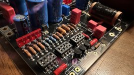
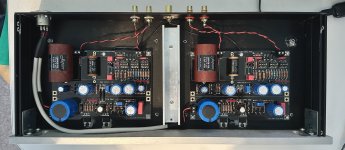
Everything went together without a hitch, thanks in large part to Teabag's painstakingly curated kit. I used some film caps I already had on hand, hence the bit of overhang on C4. I repurposed on old 1U chassis, so I had to make a few cap swaps to fit the case. Its a very, very quiet phonostage. I initially used regular twisted pair wiring for the DC, but later switched to some screened wiring I recycled from an old Apple computer supply (It was quiet both ways). At some point I may use some screened wiring for the signal, but for now I'm happy.
Everything went together without a hitch, thanks in large part to Teabag's painstakingly curated kit. I used some film caps I already had on hand, hence the bit of overhang on C4. I repurposed on old 1U chassis, so I had to make a few cap swaps to fit the case. Its a very, very quiet phonostage. I initially used regular twisted pair wiring for the DC, but later switched to some screened wiring I recycled from an old Apple computer supply (It was quiet both ways). At some point I may use some screened wiring for the signal, but for now I'm happy.
Attachments

- Home
- Source & Line
- Analogue Source
- Simplistic NJFET RIAA