Thank you, Salas!
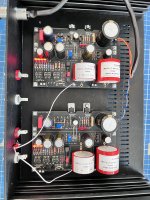
The Ohmite I can't verify, their Rating are unfortunately off visibility. Measured 1R onboard. (They came with Tea-Bags Full Kit...)
Tx primary w/ dim bulb 221 VAC
Tx secondary w/ dim bulb 32.8 VAC
The Ohmite I can't verify, their Rating are unfortunately off visibility. Measured 1R onboard. (They came with Tea-Bags Full Kit...)
Tx primary w/ dim bulb 221 VAC
Tx secondary w/ dim bulb 32.8 VAC
Everything is alright. 1Ω is our standard RD/Link for basic EMI filtering. Without dim bulb you will get bit higher Vout too.

As an aside keep in mind for power amps tube or solid state with substantial bias current, after any initial safety tests with dim bulb, finalize bias setting without dim bulb. Because it always steals some mains potential, that's its job. Especially when its a rather small Wattage bulb.
In Europe the usual general purpose test bulb is 100W.
In Europe the usual general purpose test bulb is 100W.

Wow, thank you, Salas!
(I did exactly so with my 2 power amps (and DCG3 too), biased them without dim bulb device, which is a 60W bulb 🙂 )
Now comes the fun part, finalizing the UFSP! Unfortunately, it looks like I won't have a lot of free time, too many too good jobs are waiting for me, so my slow-building practice will be even slower!
Hi all I have order a kit and will soon start to build. But I have a concern about my stylus its the old Otfofon MC20 mkII and also an Ortofon stm72 to handle the extremly low output of about 0,07mV. The stepup gain 60dB so ut will be useful in a MM RIAA stage. It sounds really wonderful. I have used it with an DIY Le-Pacific stage and also with Quad 34pre with good result. But how to set it up with this great RIAA? With or without stepup and what configuration will be good?
Ortofon STM72 Frequency response: 10Hz-50kHz, Voltage ratio: 1:60, Impedance ratio: 1:3600, Pick-Up Impedance: 2-3 Ohm, Recommended load Impedance for stereo: 47kΩ.
Ortofon MC20 mkII specs in picture

Looking forward for any suggestion.
Ortofon STM72 Frequency response: 10Hz-50kHz, Voltage ratio: 1:60, Impedance ratio: 1:3600, Pick-Up Impedance: 2-3 Ohm, Recommended load Impedance for stereo: 47kΩ.
Ortofon MC20 mkII specs in picture
Looking forward for any suggestion.
Hi, the Ortofon STM-72 step up has also been reported as 35dB gain. That's 56 times multiplication if not bang on to its 1:60 spec. Brings a 0.07mV MC 20 MkII to 3.92mV worst case. Thus, set the UFSP phono for MM mode (40dB) & 82k R1 input load, utilizing the STM-72. Gives 26Ω reflected load to your 2.5Ω cartridge that way. Not loading it down.
Also treat well the old STM's RCAs with contact cleaner. Including the captive output male ones.
LMC high sensitivity direct mode in the UFSP is going to give useful output signal with 0.25mV carts the weakest practical I would say.
Also treat well the old STM's RCAs with contact cleaner. Including the captive output male ones.
LMC high sensitivity direct mode in the UFSP is going to give useful output signal with 0.25mV carts the weakest practical I would say.
Of course you are right. 56-60times. Not dB gain. And thanks for suggestion. I will try it out. Also will use a Sumiko blue point evo III low cart.0.5mVout would also fit without stepup?
Thanks alot Salas for all help.
Thanks alot Salas for all help.
The Sumiko 0.5mV can be used straight into the UFSP either in the 56dB MC or 61dB LMC set-up mode. Whichever your system sounds best with, regarding most suitable phono output signal level. Try both settings. The DIP switches are practical for doing that.
Also have Rx3 300 Ω and Rx4 110 kΩ to can try for its loading instead of just 82 kΩ R1 reserved for the special case STM-72 + MC 20 MkII combination.
Because R1 is always in parallel, with Rx4 engaged a cart gets to see ~47 kΩ. With Rx3 engaged 299Ω. Your cart has 28Ω internal impedance and 47k is a general purpose recommended load so both those loadings are valid and useful to have.
You are welcome. To sum up, install Rx1 100Ω Rx2 200Ω Rx3 300Ω Rx4 110kΩ R1 82kΩ and you should be load flexible enough for general purpose MM & HMC or various common case MC, and surely specific to your now carts + SUT.
So it seems that today wasn't going to happen. Another delay for finishing this project.
My CnC is loosing track of it's one axis and I get not enough accuracy to finalize the front and rear face plates.
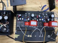
At least the bottom plate holes where correct and it starts to take shape.
Will come back with the plates drilled and engraved.


My CnC is loosing track of it's one axis and I get not enough accuracy to finalize the front and rear face plates.
At least the bottom plate holes where correct and it starts to take shape.
Will come back with the plates drilled and engraved.
Hello,
I just gave power to the phono and it seeams that something is wrong.
On the Left channel, the leds on ultrabib are OFF but the leds on the phono are ON
The V comming from Raw PSU is 40.3v
The V on the output of UBib is 32v flactuating
the V on the phono is T.P. 9.1v constant
On the Right channel, the leds on ultrabib are ON and the leds on the phono are ON
The V comming from Raw PSU is 39.4v
The V on the output of UBib is 36.98v constant
the V on the phono is T.P. 9.15v constant
Any ideas on what might be wrong on the left Ultra Bib???
Attachments
First set the switches to the sensitivity you prefer. So there's a valid circuit configuration. Power on to see if something changed with voltages and lights.
If still the same:
Start with comparing the orientation of the non working Ubib Leds to the working ones in the other Ubib. Even if one is put wrong or it died by long soldering their chain breaks and no current passes.
On the lit right channel Ubib also turn its trimmer. To test for full functionality. Try adjust it down to 33V regulated output.
Next check is for successful isolation of Mosfets metal tabs to chassis. Continuity mode beeper on DMM must stay silent when probing between tabs and their screws.
Lastly a general comparison of correct semiconductor types in correct places between working and non working sections. Starting with reading print on the Mosfets.
If all the above basic construction checks reveal nothing obviously wrong then the plot thickens. Bad component hunt season starts.
If all the above basic construction checks reveal nothing obviously wrong then the plot thickens. Bad component hunt season starts.
I'm closing in. Last thing missing is the wire-connection between Ubib and Ufsp...
Hesitated to switch it on. Should I first test with ufsp not connected (Ubib only)?
Trimpots to be set to ~centre before turning it on?
Got a bit lost in the search for the settings to accomodate a AT33PTG/II ?
Hesitated to switch it on. Should I first test with ufsp not connected (Ubib only)?
Trimpots to be set to ~centre before turning it on?
Got a bit lost in the search for the settings to accomodate a AT33PTG/II ?
Attachments
- Home
- Source & Line
- Analogue Source
- Simplistic NJFET RIAA