
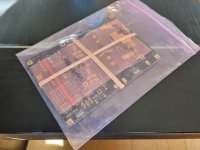
I don't see your boards to ground.you should ground them.Just adding my completed build to the collection. Only has about 2 hours of play on it, but wow, so much more open, detailed and effortless than my previous phono stage (Hagerman Bugle 2). Noticeably deeper darker background too. I do have a tiny bit of hiss coming through my system from it, but that’s about it.
View attachment 1167961View attachment 1167962
I ran my ground post direct to the chassis star ground since it was in the same case. The boards are grounded to the power supply with the black wires.
But the Raw PSU board lacks a wire to the chassis star from its PE (protective earth) point?The boards are grounded to the power supply with the black wires.
What cartridge and TT you use?Only has about 2 hours of play on it, but wow, so much more open, detailed and effortless than my previous phono
Im also planning on doing my preamp in 1 chassis. If i separate the pregulator from the amp board i can use only half of the chassis. The power section can be shifted the other way, creating a space in between with two plates. Will this give me any advantages in noise compared to steves layout?

Maybe, depends on transformers. In general distance is your friend. I have built the FSP at 62db gain on separate enclosures for raw PSU and phono stage. Placing the PSU enclosure near the phono box, at about 5-8 cm distance could produce some interference if memory serves me right.
Yes, distance is your best friend for minimizing danger of possible hum field interference. Steve uses a 3.6mV MM cart. He set correct 43dB gain for it. Judging from the ON positioned switches I saw in his photo. Medium gain is more secure against hum intrusion than higher sensitivity for MC or LoMC.
His careful build, well shielded transformer, medium sensitivity, helped for no hum in a single box installation. Even with simple twisted pair signal wiring.
The higher the sensitivity more sneaky factors show up. IEC socket and primary wiring also emit. RCA connectors can pick up some. Mains cables separation from interconnects and keeping good distance from other gear having big mains transformers like power amps and PSU boxes are also important considerations.
I was considering two 2x18v 80VA transformers, because i could buy them for a good price from a colleague. But since im going for a single chassis i think its better to go with a single 2x30v 50VA transformer, which gives less interference to start with. Then use the above layout and have shielded wire for the signal cables. Think that will do the trick. For now i will use the amp with an ortofon bronze (5mV) so wont be that sensitive. But maybe one day i will step in to the world of MC cardridges.
Would a custom shield made of MuMetal be feasible? (Since it is very sensitive to mechanic stress, I don’t know if cutting and eventually bending it would make it lose its „shielding-properties“?)
The other thing are the wires—this rather concerns my build—a coaxial wire is not a shielded wire, right?
The other thing are the wires—this rather concerns my build—a coaxial wire is not a shielded wire, right?
Every coaxial wire is a shielded wire, but not every shielded wire is a coaxial wire. Basicly a coaxial wire a single conductor shielded wire.
Sounds like a good plan. The 50VA transformer must be magnetically shielded type. Cylindrical ferrometal casing adds shielding to a toroid but the main measure is a flux band they put directly to the transformer's periphery. Many times behind the outer insulation and not easy to see. Makes a shorted turn mostly opposing the horizontal spread of the field. If it doesn't have it you can use self adhesive copper tape to dress its circumference.I was considering two 2x18v 80VA transformers, because i could buy them for a good price from a colleague. But since im going for a single chassis i think its better to go with a single 2x30v 50VA transformer, which gives less interference to start with. Then use the above layout and have shielded wire for the signal cables. Think that will do the trick. For now i will use the amp with an ortofon bronze (5mV) so wont be that sensitive. But maybe one day i will step in to the world of MC cardridges.
Most easy to get in the netherlands is amplimo. They are good quality transformers but i cant find anywhere on their website if they are shielded or not. No casing for sure, but not sure on the other shield.
Looks like toroidy audio grade (not the supreme) has the same price as the amplimo. Maybe i'll have a look into that.
Looks like toroidy audio grade (not the supreme) has the same price as the amplimo. Maybe i'll have a look into that.
I mailed amplimo, their stock range doesnt have shielding in it. A one off custom will be a bit to expensive. So i guess i will go with the toroidy transformer.
Teabags PCBs came in the mail today, excellent quality! Time to slowly collect parts 😁
Teabags PCBs came in the mail today, excellent quality! Time to slowly collect parts 😁
Attachments
Hi Salas,
in the last version can i replaced Q1,Q2 by 2sk170BL or 2sk146 and Q7 by 2sk170? thank you! Maxpou
in the last version can i replaced Q1,Q2 by 2sk170BL or 2sk146 and Q7 by 2sk170? thank you! Maxpou
Hi Max,
Half 2SK146 double is equivalent to a single 2SK369 so yes use a 2SK146 for Q1 Q2.
Q7 can be a 2SK170BL but use low IDSS not to drop too much voltage across the R18 2.2K RC filter resistor. So there will remain enough voltage for Q7 and the LEDS. No less than 15V at C5 in respect to ground. Else use smaller value R18.
- Home
- Source & Line
- Analogue Source
- Simplistic NJFET RIAA