Fuse question:
According to the build-guide’s schematic, I shall use a 300 mA fuse…
May I ask why the fuse is after the switch?
Thank you
According to the build-guide’s schematic, I shall use a 300 mA fuse…
May I ask why the fuse is after the switch?
Thank you
Say someone relies on a device is switched off and proceeds to check its fuse. But the power cord is left connected to the mains. If the fuse is wired before the power switch there's a chance he can touch live spots in the fuse assembly.
How many VA in total transformer(s) you will use?According to the build-guide’s schematic, I shall use a 300 mA fuse…
I recommend you test the Raw DC board's outputs with 470 Ohm 10W dummy load resistors before connecting the rest of UFSP to it. So we see about best RDLink value for those transformers. We want to keep loaded raw DC below 48V.
300mA slo-blo fuse should take the two 30VA transformers inrush on European mains because there's RDLink too which damps the reservoir caps. But if it proves too closely fused for them tripping from time to time without a real reason, you are allowed up to 750mA primary fuse for 60VA in total.
300mA slo-blo fuse should take the two 30VA transformers inrush on European mains because there's RDLink too which damps the reservoir caps. But if it proves too closely fused for them tripping from time to time without a real reason, you are allowed up to 750mA primary fuse for 60VA in total.
By the way
The switch before fuse practice in my PSU schematics isn't necessarily common or intuitive I see, especially in older equipment, but it seems best.Say someone relies on a device is switched off and proceeds to check its fuse. But the power cord is left connected to the mains. If the fuse is wired before the power switch there's a chance he can touch live spots in the fuse assembly.
Thanks again!
I was wondering a bit as there are IECs having a fuse, but no switch.
( https://www.hypex.nl/product/power-connector-iec-60320-c14-fused/118 )
I know it’s a picky point as it’s not possible to get hit by fumbling with the fuse… Anyway I go a slightly different way and I prefer having the fuse after the switch.
Will source me a 10W resistor as per your recommendation and get on another build-journey… 🤗
@RickRay haha, yesofcourse, that makes sense...
Completely different something that occurred to me: In the
Folded Simplistic PCB build guide's BOM, a RG174 coax wire is recommended... as this thing has a steel core, I'm wodering about that? (I mean, I more often than not read 🙄 that steel-core isn't well suited for signal-lines... ? OTOH it's a BOM of master Salas' hand?
Really? I've used RG174 a lot in tube guitar amp builds (the guitar amp builders love it—has the right level of flex/no-flex to stay put-ish)...Every spec I've seen listed states "bare copper " for the "inner conductor"?
Well, I not at all sure…
Everywhere I look it sez steel, but then there’s salas as well as that recommendation (was in a magazine comparable to stereophile or 6m)…
And your and others liking/impression…
Or is it just OCD?
https://www.koax24.de/storage/datasheet/de/050239_Datenblatt_RG174.pdf
https://asset.conrad.com/media10/ad...sser-267-mm-rg174-au-50-schwarz-meterware.pdf
https://www.pasternack.com/images/productpdf/rg174a-u.pdf

Wow. Brand differences?
https://www.awcwire.com/belden-coaxial-cable/low-loss-50-ohm-wireless-rf-cable/belden-rg174
(But wait... on Belden's site they say this: "Solid Bare Copper Covered Steel Conductor", what?)
Usually I'm using Mogami or Canare, no particular reason—It seems that finding details on core materials for Mogami isn't super forthcoming... IDK.
I'm not convinced any of this matters... or is audible...but... fascinating.
Looks like! Grrr.
I thought those RGnumber were sort of a reference.
I'm very much on your side concerning audibility of technical details. Core materials is something I was more cautious. So instead of a RG174 I went with Mogami 2520, very nice to work with! (In the COAX-context that is)
I thought those RGnumber were sort of a reference.
I'm very much on your side concerning audibility of technical details. Core materials is something I was more cautious. So instead of a RG174 I went with Mogami 2520, very nice to work with! (In the COAX-context that is)
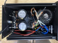
RAW PSU almost done...
Do the transformer shield (yellow-green wire) connect directly to the PE, together with the PSU?
Thank you!
Do the transformer shield (yellow-green wire) connect directly to the PE, together with the PSU?
Thank you!
Static shield cable goes directly to the mains protective earth connection together with the rest on a chassis bolt with safety grommet, yes.
Thank you Salas!
Though now you got me confused—is it the classic way, aka
PE - chassis-bolt (as star ground) - raw-PSU-earth+static shield?
(The PE-symbol on the rawpsu-board got me, made me want to connect it directly to mains PE...)
Though now you got me confused—is it the classic way, aka
PE - chassis-bolt (as star ground) - raw-PSU-earth+static shield?
(The PE-symbol on the rawpsu-board got me, made me want to connect it directly to mains PE...)
- Home
- Source & Line
- Analogue Source
- Simplistic NJFET RIAA