Wow is my first impression!Now it's good
About the output capacitor's value, its not really written in stone, most of the subsonic cut curve is shaped from the previous 0.1uF coupling.
But the output cap completes it. In combination with the line stage's input impedance.
Smaller bass reflex speakers because not deeply tuned don't have enough VLF port resistance to control the cone. Imperfect arm cart resonance or a somewhat feedback prone turntable installation can promote that further etc.
In other words, you can use a higher value but judge in the context of your system. Keeping subsonic control. Test and see.
But let us know how you liked it as it is in your last picture first. With what cart and turntable etc.

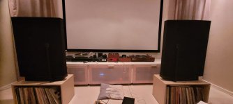
Sounds great, and is so quiet. I went for the 55-56 dB gain.
Gear:
Lenco L78 with separate arm base fitted with a Grace 707 tonearm and a Sumiko point special evo iii MC.
Or (I have implemented 2 inputs)
Clear Audio entry level TT (forgot the name) with Clear Audio Virtuoso cartridge MM.
I'm listening to the the CLEAR Audio as I write this.
Rest of the system is a Tram w.o.t preamp, First Watt F5Turbo monoblocks and Quad ELS 63.
😊👍
Mikkel
Attachments
Very nice result & system. Congratulations! In about two days play you will know more sonic details.
Thank you for the advice. I have repowered the power supply, measured it at plug terminals on chassis mount xlr jacks in phono unit, all still measures as before on both sides of Raw power supply.SAE 1000LT has a smooth sound reputation.
Configure for 43dB gain and 47k load impedance.
Sensitivity setting (S5-S12):
HiMC 43dB
S7 ON S11 ON all others OFF
Loading:
S1-S4 all OFF input load is 47k
Next, hook up shunt, set to starting voltage, then to phono board for final adjustments.
Almost there.
Russellc
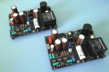
Say, M3 hardware looks a tad tiny to use for mounting M1 and M2 to floor of case. On the other hand, I have M3 in my possession and the transistors are small....what did everyone here use?
Russellc
Russellc
If they are TO220 parts the standard TO220 mounting kit is needed, ie heatsink needs 3.5mm hole, top-hat insulating washer and M3 bolt, with silpad or equivalent. For instance https://uk.rs-online.com/web/p/heatsink-mounting-accessories/7128225Say, M3 hardware looks a tad tiny to use for mounting M1 and M2 to floor of case. On the other hand, I have M3 in my possession and the transistors are small....what did everyone here use?
Russellc
Perfect. They are small devices! Thanks.If they are TO220 parts the standard TO220 mounting kit is needed, ie heatsink needs 3.5mm hole, top-hat insulating washer and M3 bolt, with silpad or equivalent. For instance https://uk.rs-online.com/web/p/heatsink-mounting-accessories/7128225
Russellc
Bloody hell the DIY course stroke again, I'm missing a part.
I have two matched PF5102 and 5 unmatched. I need one extra PF5102 and you know the story
I do have the previous 2sk117 (and few extras 2sk170) but I think the circuit is optimized for PF5102 (having the voltage drop leds).
Anyone in EU having a spare ?
I have two matched PF5102 and 5 unmatched. I need one extra PF5102 and you know the story
I do have the previous 2sk117 (and few extras 2sk170) but I think the circuit is optimized for PF5102 (having the voltage drop leds).
Anyone in EU having a spare ?
Attachments
Thanks for the quick reply Nick.For Q7s you can substitute with 2SK117s
Really ? I had the impression that the change of led positioning was for PF5102 specifically.
For now, I will use 2sk117 but does PF5102 make any difference in sound quality ?
Q7s don't have source pin degeneration resistors so 2SK117s will go G+S shorted in the specific PCB spot as much as PF5102s no matter the DGS vs DSG difference in pin order between the two types. All you need is two close enough IDSS JFETs. +/-10% is OK. This Toshiba type is excellent for the purpose of constant current feeding the four Vref LEDs as well, no worries.
Thanks again,
Forgot to mention that my 117 jfets have IDSS of 4.5mA (both), I guess that they'll do.
Tomorrow I'll have it running, I reckon.
I have the old BIB psu also and an A/B testing will be done.
Back to my hole now.
Forgot to mention that my 117 jfets have IDSS of 4.5mA (both), I guess that they'll do.
Tomorrow I'll have it running, I reckon.
I have the old BIB psu also and an A/B testing will be done.
Back to my hole now.
Last edited:
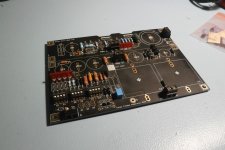
Thanks, almost done now, placing those Rhopoints was time consuming. I have to make a small pcb for the trimmer, I used my 10K for another project and left you only 1Ks so I'm putting a resistor in series.
I'm gonna use a 6800uf (raw) and 2200uf (local) combination for now. Another 6800uf for local maybe too much ?
I'm gonna use a 6800uf (raw) and 2200uf (local) combination for now. Another 6800uf for local maybe too much ?
Attachments
Interesting alternative parts except Rhopoint resistors I see, like a Miflex KFPM interstage and that Rike Audio rectangular output capacitor.
Your 1k UBiB trimmer when missing the full spec 10k will naturally narrow the adjustable rail range. Let's hope it will allow enough critical range to set T.P.
2200uF local input reservoir on the UBiB shunt will still work for noise spec. When missing the 4700uF BOM cap can possibly differentiate the tone somewhat but not crucially so.
Rike's is Aluminium foil in PIO while Miflex is Copper foil in Polypropylene
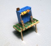
I'm gonna put the resistor in a base so I can easily change it, hopefully it will do the trick
The latest BOM calls for 4700uf (RAW) plus 4700uf (local), I don't have such values for Mundorfs, it's either 6800uf + 2200uf or 6800uf + 6800uf.
I'm gonna put the resistor in a base so I can easily change it, hopefully it will do the trick
The latest BOM calls for 4700uf (RAW) plus 4700uf (local), I don't have such values for Mundorfs, it's either 6800uf + 2200uf or 6800uf + 6800uf.
Attachments
Hello, where is the right place for a phase switch? I am now wiring a MC stepup transformer to an external box.
I also plan to add another switch, stereo to mono transformer-based (centre tapped 600R to 600R) to the phono preamplifier soon. And again, not sure where it must be placed.
I'm sorry if it's off topic or already discussed. No more 'search this thread' in Diyaudio site?
Jordi
I also plan to add another switch, stereo to mono transformer-based (centre tapped 600R to 600R) to the phono preamplifier soon. And again, not sure where it must be placed.
I'm sorry if it's off topic or already discussed. No more 'search this thread' in Diyaudio site?
Jordi
When you start a search (top of the page) automatically appears a drop down menu, as default 'Everywhere' is selected. Just select 'this thread' and your search will be limited to this thread. You just haven't noticed it, it's little bit hidden.No more 'search this thread' in Diyaudio site?
A switch to reverse the SUT's primary should work for flipping absolute phase I guess. If it is a floating primary. But to have switch contacts there maybe degrades the signal somewhat. Is it necessary to have a phase reverse facility?
- Home
- Source & Line
- Analogue Source
- Simplistic NJFET RIAA