Many meters need a sort of zeroing for accurate low resistance reading. Δ button. Some have it some not. Accepting approximation. In high ranges the test leads resistance is a negligible % anyway. Your 5.6Ω resistors reading as 5.8Ω should be in spec.
If I don't zero it on shorted leads with the REL Δ button (then it stops auto-ranging) my Fluke 87V adds 0.12Ω-0.15Ω from Brymen silicone leads. So your $20 meter reporting a 5.6 1% part as 5.8 is no slouch.I guess these "Southwire" DVM's just don't like very low ohm resistors.
Funny thing is my $20 meter which is not an auto ranging meter measured "5.8ohms" . Go figure
If you don't have the delta function, just short the leads, note the reading, and subtract it from you low ohm readings. I come from an automotive background, we had to do that to measure injector and ignition primary windings.
Thanks for all of the replies. They say you never forget anything, it is the Recall that gets in the way. It took about 18 hours for me to recall that if I short the leads and subtract the difference !!!!!!!!!
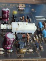
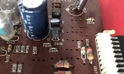
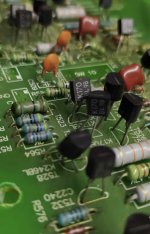
Both of the Auto Ranging meters measure .1 or .2 difference. The $20 "Dial Your Own" measured 5.6 . Got all of the resistors soldered onto the board next step "LED" orientation.
Lets see.........anode goes to big side or base of "arrow"?? Reading the 12 and 15 on the diodes about drove me crazy. Had to get the teenaged Daughter to read that one.
Man I picked the wrong year to give up "Beer" for Lent...
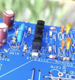
Short leg is cathode in any LED and rectangular pad is cathode in the phono PCB. ->| Arrow's tip side is cathode in the shunt reg's PCB where both LED pads have same circular shape.
Last edited:
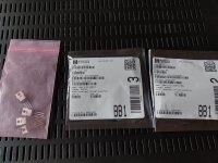
Just as I figured. New parts arrived, look what cat dragged in:Oh boy. Just got the CMR caps and other small parts to finish this phono pre. I am bent to finish this and my also basically done DCG3 preamp
Opening case of the phono, I noticed the only board parts not yet soldered in, the M1 and M2 pairs and their small bag were not to be seen.
As I recall these were some of the "super matched" items and are irreplaceable. I bought the "big" kit. If this is so, I will find them, I thought they might be in the DCG3 case, but nope. I'm sure I will locate, there are just a lot of places to look.
Otherwise, perhaps they are an easy to replace part? Rarely do I miss place those, it's the difficult ones I put "somewhere safe." Usually, that is in the case. I wonder if I took them out when I opened to solder C3 and Ç4, the big CMR caps. Nutz.
So, must find these, or easy to replace. I think I already know the answer. I have a lot of boxes to go through!
Russellc
Attachments
I got it!!! I will place these parts in this box on the shelf. It’s a safe place!!!!!
I have NEVER done that🙄
I have NEVER done that🙄
你好,亲爱的和热情的萨拉斯,你的许多想法丰富了我的生活,给我带来了快乐,谢谢你!我偶然得到了一个古董TVV47唱机放大器,我附上了一个路线图,它是TVV46的高级版本,在这里,我想问我是否要将图片中的T1更改为2sj74(BL,idss= 6.8ma),T2更改为2sk170(BL,idss= 6.8ma),因为我手头上只有几对,但我是幼儿园水平, 我想尝试一下,但我不知道如何设置合适的工作点,你能给出建议吗?我知道这有点自以为是,但我真的很想看看衰减的RIAA和反馈RIAA的感觉如何不同。节日快乐!

.JPG")

"Hello dear and warm Salas, your many ideas have enriched my life and brought me joy, thank you! I got an antique TVV47 phono amplifier by chance, I have attached a roadmap, it is an advanced version of the TVV46, here I want to ask if I want to change the T1 in the picture to a 2sj74 (BL, idss=6.8ma) , T2 changed to 2sk170 (BL, idss=6.8ma) because I only have a few pairs on hand, but I'm kindergarten level, I want to try it out, but I don't know how to set a proper working point, can you give any advice ? I know it's a bit opinionated, but I'd really like to see how decayed RIAA and feedback RIAA feel different. Happy holiday!"你好,亲爱的和热情的萨拉斯,你的许多想法丰富了我的生活,给我带来了快乐,谢谢你!我偶然得到了一个古董TVV47唱机放大器,我附上了一个路线图,它是TVV46的高级版本,在这里,我想问我是否要将图片中的T1更改为2sj74(BL,idss= 6.8ma),T2更改为2sk170(BL,idss= 6.8ma),因为我手头上只有几对,但我是幼儿园水平, 我想尝试一下,但我不知道如何设置合适的工作点,你能给出建议吗?我知道这有点自以为是,但我真的很想看看衰减的RIAA和反馈RIAA的感觉如何不同。节日快乐!
Hello, please translate and post in English only.
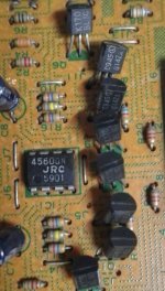
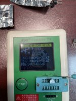
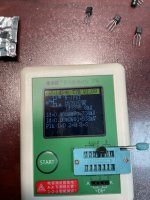
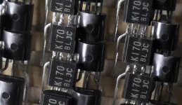
Unfortunately you can't drop JFETs in a BJT transistors finished design. The JFETs in your picture have wrong print details, possibly copies, better avoid using them in general.
This is how originals look
https://www.diyaudio.com/community/threads/replacement-for-toshiba-2sk170-2sj74.317563/post-5732244
https://www.diyaudio.com/community/threads/replacement-for-toshiba-2sk170-2sj74.317563/post-5732244
hi,Salas。 Thank you for your quick reply, you said the tube package details I have not noticed, I took a closer look today, thank you!
I flipped through some of the early Japanese circuit boards today, and found that the K170 pipe body of Toshiba's period had a font face that was slightly concave and convex, and the white print was consistent with my tube, and now I can buy the K170 is a smooth face, laser lettering, please see the picture, it may be caused by different production dates, my feelings, for reference only
Attachments
I'd now like to build a dual TVV47 series with breadboard 2sj74 (instead of BC253) and 2sk170 (instead of Bc173), but it won't build a new tube to work at, and I'll try
Last edited:
Can PF5102 be used for Q5 and Q6 the CF? Can anything else be used? Just don't have any K170 for this position.
- Home
- Source & Line
- Analogue Source
- Simplistic NJFET RIAA