For R8, I have 39 or 47. Is there a best choice between these?In UFSP BOM - R8 and R11 "depends on idss of Q4 and Q5" see sheet. Not sure what sheet?
In FSP build guide - Q4 idss 8.2 - 8.5, Q5 idss 7.5 - 8.5, Q6 idss 9 - 10: I can easily find these values from my LSK170B supply. If I use these values(tested with DCA75) do I stick with R8=43 ohms and R11=1.5kOhms?
CorrectThank You, and I assume my LSK170B Q7 should be 4.7-7ma .5 difference between channels, same as PF5102.
Thanks for all of the support. I'm ready to start up. I have 44.7V raw DC unloaded.
Should I start with Raw DC connected to UBIB and UBIB not connected to preamp.
Also I dont have a TT rig at the moment(Listening test will be at a friends later) so what tests can I perform with signal Generator and scope..
Should I start with Raw DC connected to UBIB and UBIB not connected to preamp.
Also I dont have a TT rig at the moment(Listening test will be at a friends later) so what tests can I perform with signal Generator and scope..
You could proof test the 1.3s outputs by loading them with 560R or 680R 2W (or 5W not getting so hot) dummies instead of the phono channels.
For signal testing you could pass 1kHz 100mV RMS generator sinewave output through 1k series & 10R to GND voltage divider, use it as 1mV test signal to the phono input. It cuts the generator's noise. Then look for healthy phono signal output at least in the 300mV RMS range and compare the channels gain matching on the scope. Don't use other frequencies unless you got some anti-riaa filter.
For signal testing you could pass 1kHz 100mV RMS generator sinewave output through 1k series & 10R to GND voltage divider, use it as 1mV test signal to the phono input. It cuts the generator's noise. Then look for healthy phono signal output at least in the 300mV RMS range and compare the channels gain matching on the scope. Don't use other frequencies unless you got some anti-riaa filter.
Using 600 ohm resistor, It looks good so far. - Channel 1, DC raw loaded = 41.5v, regulator range 28.4 - 39.5V. Channel 2, DC raw loaded =41.5v, regulator range 28.2 - 39.1V. led trios come up matched brightness.
Im not liking my signal with 1k and 10 resistor. its more noisy with the resistors than 1mv straight out of the signal generator but its noisy straight out as well. maybe leads are picking up. I'll skip that step for now..
Anyway, both channels 34V from ubib and dialed in 4v at the test points.. listening is next step..
Anyway, both channels 34V from ubib and dialed in 4v at the test points.. listening is next step..
In this case use coax test signal cable and put the divider resistors in a metal barrel RCA at the receiving end for shielding. Its a matter of impedance as well. It is a 1:100 10 Ohm source impedance divider. If not terminated with a 100 Ohm to 300 Ohm as the phono does, but simply checking its test signal with a scope's probe, which certainly shows very high impedance, it will pick up more interference. Anyway, if you saw strong signal gain at the phono's output, even noisy, means it works.
Edit : the poweramp has an input impedance of 26K, that is probably too low.
What is the Z out of the UltraFSP?
What is the Z out of the UltraFSP?
Last edited:
Zout is 50Ω but with small current reserve. As much as Q5's Idss. The output capacitor value is also calculated for 20k minimum. Thus better avoid long high capacitance interconnects and a low Input impedance next stage. Use a higher value C4 if unavoidable.
I will eventually make up suggested test cable for testing second UFSP, maybe a third one and this first one later.. Thanks!In this case use coax test signal cable and put the divider resistors in a metal barrel RCA at the receiving end for shielding. Its a matter of impedance as well. It is a 1:100 10 Ohm source impedance divider. If not terminated with a 100 Ohm to 300 Ohm as the phono does, but simply checking its test signal with a scope's probe, which certainly shows very high impedance, it will pick up more interference. Anyway, if you saw strong signal gain at the phono's output, even noisy, means it works.
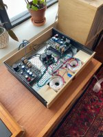
UFSP was delivered and worked in system perfectly. Sound is totally hi-end. Treble, dynamics, resolution, everything! temporary case as it will eventually go into 2 boxes of Slimline 3u with DCB3 and a DAC.
Many Thanks!
Attachments
What is suggested(proper) grounding connection for TT if it has one?
In one case should raw dc, earth, preamp board and TT ground be connected together?
In 2 cases with DC cord then only choice is TT ground to preamp board ground together unless PSU chassis has ground has a ground link to Preamp chassis.
In one case should raw dc, earth, preamp board and TT ground be connected together?
In 2 cases with DC cord then only choice is TT ground to preamp board ground together unless PSU chassis has ground has a ground link to Preamp chassis.
Congratulations for your success. You are welcome. Nice touch with the wooden panel, fits to the picture's installation environment. What C3 C4? Tell us a few words about that system too.I will eventually make up suggested test cable for testing second UFSP, maybe a third one and this first one later.. Thanks!
UFSP was delivered and worked in system perfectly. Sound is totally hi-end. Treble, dynamics, resolution, everything! temporary case as it will eventually go into 2 boxes of Slimline 3u with DCB3 and a DAC.
Many Thanks!
You can eventually take very clean phono measurements on the scope with the aid of a shielded test signal line and a shielded divider. Talking from experience because I have had 16-24 bit FFT in LMC mode without harmonic noise spikes even. But tiny signal lab work is intricate and takes patience to solve details, I recognize that.
The TT's earth wire spade goes to a binding post. Non insulated post to chassis. Convenient place to tie the signal boards ground lines there too. At its back. There is a special pad labeled "G" in front of each phono board. Bring no further ground lines to the phono chassis from other places. For the PSU chassis the Raw DC board has a protective earth pad for single connection to its mains earth and chassis point.What is suggested(proper) grounding connection for TT if it has one?
In one case should raw dc, earth, preamp board and TT ground be connected together?
In 2 cases with DC cord then only choice is TT ground to preamp board ground together unless PSU chassis has ground has a ground link to Preamp chassis.
For single chassis, which I don't recommend, if you will get hum problems and it isn't because of the Tx field and/or the mains wiring field, lift one channel's ground line from the binding post to see if it helps.
Hello everyone. This preamp is built according to the dual mono scheme. Perhaps this has already been discussed in this topic, but I could not find a very large amount of information (955 pages). If you have any questions, please tell me.
Question 1. If there are separate earths in the preamplifier, then when connected to an amplifier with a common ground (stereo option),
we get a loop, right? How to properly dilute the earths in the preamplifier so that both the double is saved and the loop is not obtained when connected to other devices.
Question 2. This question was the reason to think about the earth. From the vinyl player there is an earth wire that connects to the Phono preamp terminal of the same name. How to get the corrector lands in double mono on this terminal? Or combine them somewhere (at the input connectors)? Then what about the double mono.
Sorry, English is not my native language. Thanks.
Hi, the separate earths in the general grounding scheme of the FSP original guide do meet in the raw supply board and in the main phono chassis. In the PSU side they use a path break and ground lift scheme. Complete dual mono would be four chassis two power chords. That scheme generally worked silently for different boxed builds. Posts #17,796 #17,797 show it and briefly explain it again. Found at few posts below the UFSP schematics link. It is not a mandatory scheme, each one can experiment and ground differently according to build aspirations and rest of system compatibility.
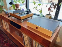
Table is LP12 Japanese clone build with Supatrac tonearm and Hanna SL Cartridge
Mezmerize Buffer, Proac clone, pair of Apex mono amps.
This coming weekend Gemme Audio VFlex Katana will reside in the space for a few months - Should be interesting
A 4way direct radiator speaker is in early design stage. Experimenting with more Power amps, including Apex A40, AA9Md and Ovation NX along with several others..
Attachments

- Home
- Source & Line
- Analogue Source
- Simplistic NJFET RIAA