Without cap multiplier, measuring C4 to GND 8,97V but I believe isn't a good reg. for a pre-pre MC....
Why you want to take out the cap multiplier. Use the circuit as designed. There is a chip reg at 9V then a filter. The cap multiplier filter eats the reg's noise by much and brings down the voltage also. Its designed to work form that final voltage.
I repeat. The amplification circuit is not designed to work from 9V, but from about 7.5V as after the multiplier.
Build & measurement pics Low MC pre-pre
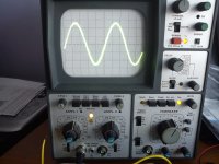
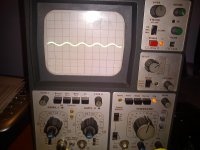
1st pic right channel
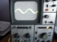
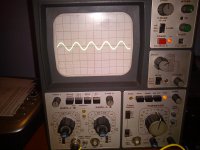
2nd pic 1kHz direct audio generator 30dB attenuation
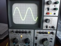
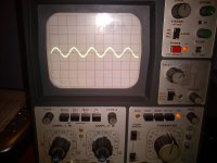
3rd pic lefht channel
probe x1
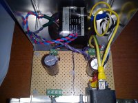
4th pic Low MC pre-pre including capacitance multiplier
5th pic R-Core separate PSU
Are the measurements OK?
1st pic right channel
2nd pic 1kHz direct audio generator 30dB attenuation
3rd pic lefht channel
probe x1
4th pic Low MC pre-pre including capacitance multiplier
5th pic R-Core separate PSU
Are the measurements OK?
Attachments

Last edited:
I can see higher output than input. How much exactly, channel matching looks good, you know your numbers.
Voltage gain in dB = 20 log Vout/Vin
Now I only need to know how calculate the volts with the scope, help please?
Now I only need to know how calculate the volts with the scope, help please?
I will try to calculate:
Scope set 0.2V/cm
Direct 1kHz generator aprox. half cm = 0.1Vpp
After Low MC pre-pre aprox. 2 cm = 0.4Vpp
This gives me 12.0412 dB not 20dB
Are my calculations OK or wrong?
Scope set 0.2V/cm
Direct 1kHz generator aprox. half cm = 0.1Vpp
After Low MC pre-pre aprox. 2 cm = 0.4Vpp
This gives me 12.0412 dB not 20dB
Are my calculations OK or wrong?
Voltage gain in dB = 20 log Vout/Vin
Now I only need to know how calculate the volts with the scope, help please?
You need see 10X the input but don't feed it 100mV, feed it 1mV. If you don't have the means try it on the actual TT.
When you feed from gen's Zo Ohm to cart load value, better tap off to scope as you feed the pre so to be sure what actual input remains when comparing output to the other channel. What is the signal source impedance and what is the input pre-pre's load?
Sorry my ignorance how do you say: "what you prepare on 1Meg scope input"
Do you want that I do the measurements with the probe x1?
Do you want that I do the measurements with the probe x1?
Its simple. 600 Ohm to 220 Ohm form a 1/3.7 Lpad. So you lose much of your signal that you saw on 1 MegOhm scope channel before. To have 1mV pk-pk (0.35mVRMS) on the pre, see 3.7mV pk-pk on your scope directly from your generator first.

- Home
- Source & Line
- Analogue Source
- Simplistic NJFET RIAA